STOBER 8 | Connection
12/2018 | ID 442537.05
95
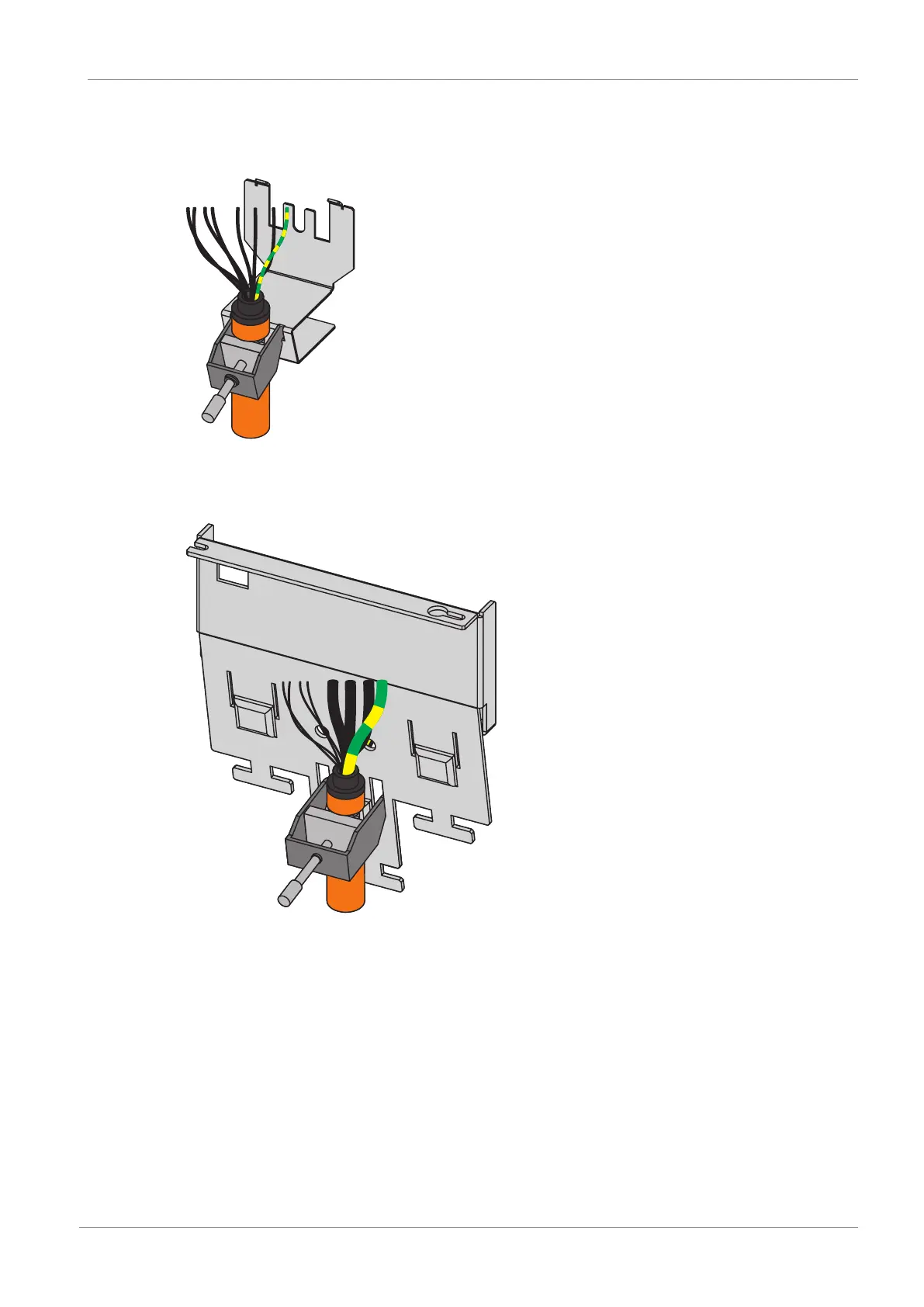
2. Sizes 0 to 2: In order to connect the motor temperature sensor, the control of the brake and
the motor itself to the drive controller, wire the cores of the power cables with terminals X2,
X5 and X20. Attach the power cable to the EMC shroud.
3. Size 3: Start by attaching the power cable to the EMC shroud. Then wire the cores of the
power cable to terminals X2, X5 and X20 in order to connect the motor temperature sensor,
the brake control and the motor itself to the drive controller.
4. Sizes 0 to 2: Attach terminal X20.
5. Connect the supply voltage for the brake to terminal X6 and attach it.
6. Attach terminals X2 and X5.
7. Optional: Connect an encoder to terminal X4.
8. Wire the enable signal (pins 3 and 4) and optional relay 1 (pins 1 and 2) to terminal X1 and
attach them.

 Loading...

