2.1. Components
1
2
3
4
5
6
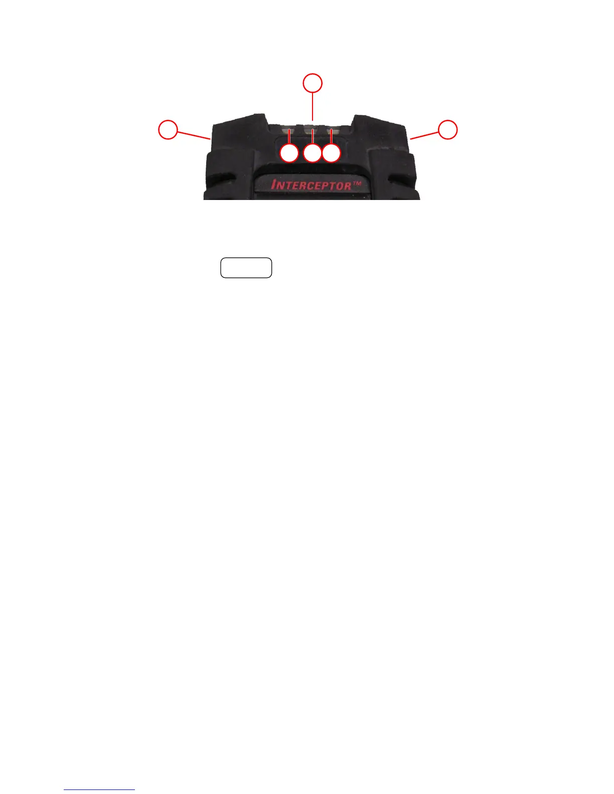
Figure 2-2. Button and LED area of INTERCEPTOR™.
holding the POWER button for approximately 2 seconds or un-
til the button label changes from “LOCK” to “UNLOCK” or
“UNLOCK” to “LOCK”.
• Switch back to the default mode from the top level of all other
modes of operation.
3. The red LED indicates a gamma alarm condition when blinking.
4. The green LED indicates the power status.
• Slow blinking indicates normal operation.
• Fast blinking indicates that the device has a USB connection and
is charging the battery.
• Faster blinking indicates that the battery is nearly empty.
• Constantly on indicates that the battery charging cycle is com-
plete.
5. If the device is equipped with optional neutron detection capability,
the blue LED indicates a neutron alarm condition when flashing.
Use any button on the I™ to change from the Unattended
Surveillance Mode (USM) to User Attended Mode (UAM).
2.1.3 Component Descriptions: Rear View
A camera, as well as a neutron detector, may be installed as optional features
in your I™ unit.
Thermo Fisher Scientific Interceptor™/en/5.1(4956)/Feb2010 5