OPTIONS & ALLIED TOOLING − DECO 7/10 − DECO 7a/10a − DECO 7e/10e
300236 en − 02/07 Chap. 19. /2
APPLICATION
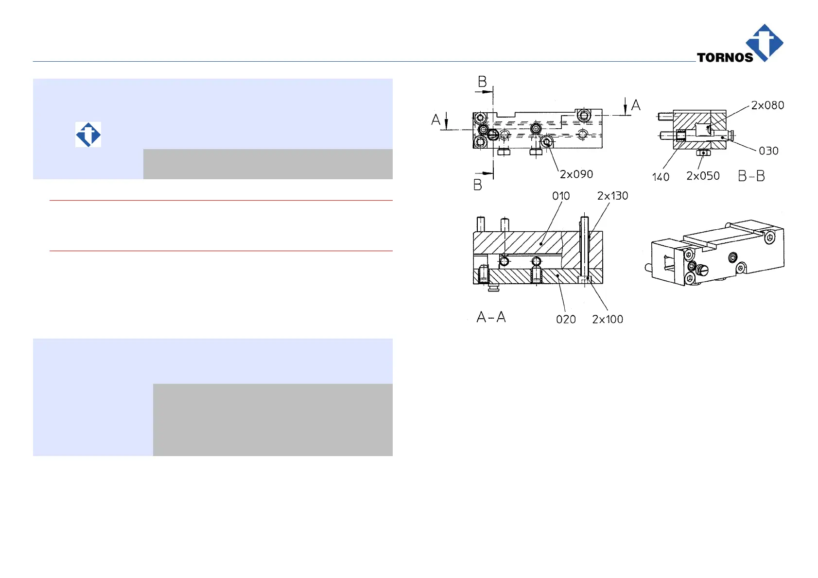
Bar Retention Claws Option comprises:
Désignation
305121 1 set of two V-claws
305129 2 removable tooolders
. Caution !
Claw the bar simultaneously with both V-claws to avoid lateral stresses
on the guidebush.
BAR RETENTION CLAWS STATIONS
On Vertical: preferably facing each other in:
T11 and T21
BAR RETENTION CLAWS GEOMETRICS
Feature Description Data
X1 ; X2
62 mm from the face
of a disengaged
V-claw
Y1 ; Y2 0 mm
Z1 22 (V-claws axis)
305129
BAR RETENTION CLAWS OPERATION
The bar retention claws system replaces other devices of bar support & reten-
tion between the main spindle and the guidebush, used in other TB products.
Mounting: on X1/Y1 & X2/Y2 gang tooling system in place of toolholder:
Clawing action: X1 and X2-axes approach to claw softly (over springs) the
opposite sides of a bar and lock it while the main spindle retreats.