g230839
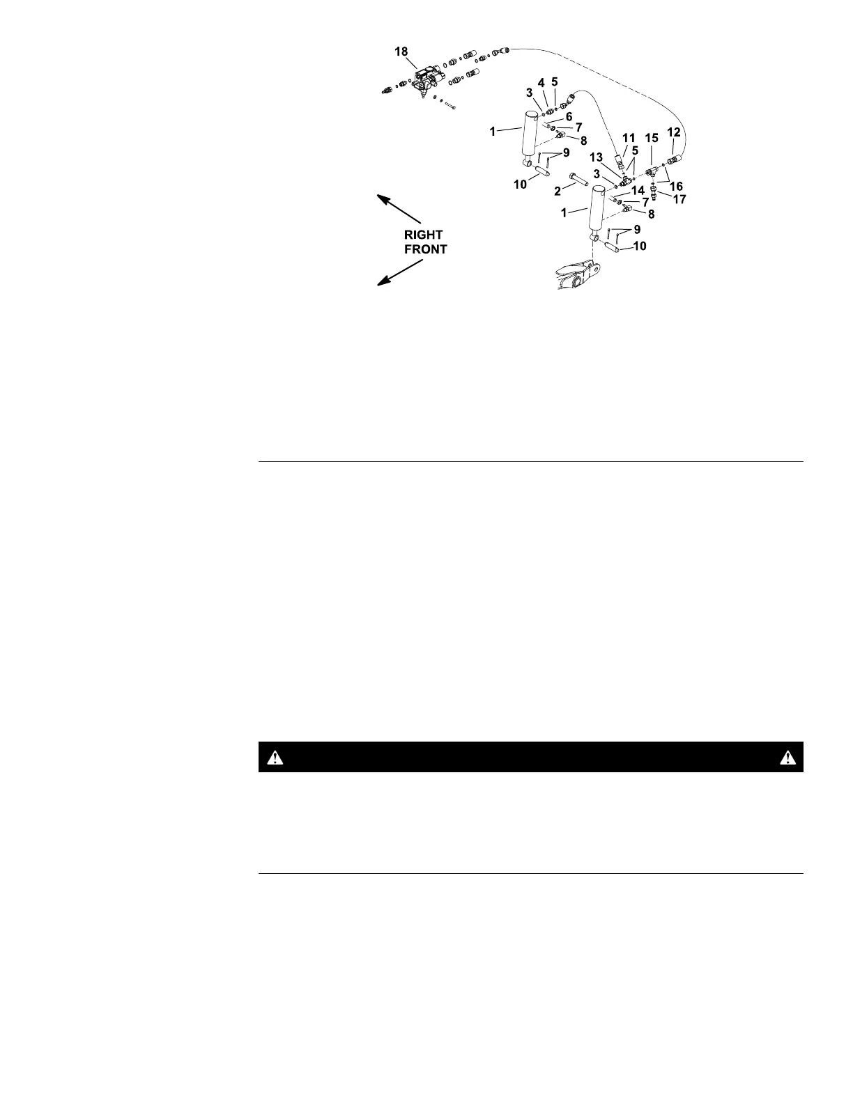
Figure93
1.Liftcylinder
7.Hoseclamp
13.Hydraulicteetting
2.Bolt8.Hosestem14.Hydraulichose
3.O-ring9.Cotterpin15.Hydraulicteetting
4.Hydraulictting10.Cylinderpin16.O-ring
5.O-ring
11.Hydraulichose17.T estport
6.Hydraulichose12.Hydraulichose
18.Liftcontrolvalve
Note:Iftheliftcylinderwearordamageoccurs,theliftcylinderreplacementis
necessary.Theliftcylindersarenotrebuildable.
Note:Onmachineswithserialnumbersabove260000001,thetestport(item
17inFigure93)islocatedontherightliftcylinder.
RemovingtheLiftCylinder
1.Parkthemachineonalevelsurface,lowerthecuttingdeck,shutoffthe
engine,settheparkingbrake,andremovethekeyfromthekeyswitch.
2.ReadtheGeneralPrecautionsforRemovingandInstallingtheHydraulic
SystemComponents(page5–77).
3.Forassemblypurposes,labelallthehydraulicconnections.Cleanthe
hydraulicconnectionsbeforelooseningthehydrauliclinesfromthelift
cylinder.
CAUTION
Beforeopeningthehydraulicsystem,operateallthehydraulic
controlstoreleasesystempressureandavoidinjuryfromthe
pressurizedhydraulicuid;refertoReleasingPressurefromthe
HydraulicSystem(page5–6).
4.Disconnectthehydraulichosesfromthettingsintheliftcylinderthatistobe
removed.Allowthehosestodrainintoasuitablecontainer.Removeand
discardtheO-ringsfromthettings.
5.Installcleancapsorplugsonthehydraulichosesandttingstoprevent
contamination.
6.Remove1cotterpin(item13inFigure92)fromthecylinderpin.Pullthe
cylinderpinfromtheliftcylinderandliftarm.
Groundsmaster
®
3280-D/3320
Page5–111
HydraulicSystem:ServiceandRepairs
05138SLRevB
 Loading...


