TestingtheRelays(continued)
g214499
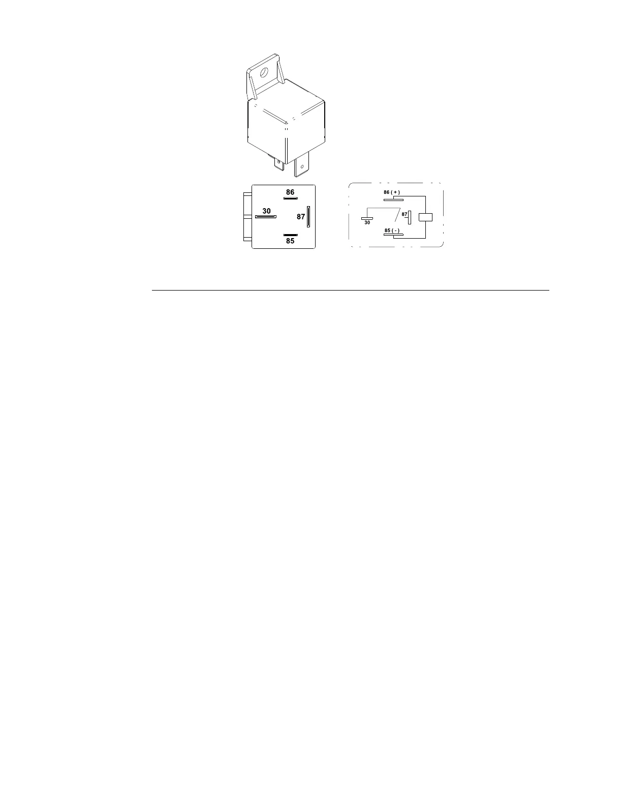
Figure162
5.Checkthecoilresistancebetweenterminalsthe85and86withamultimeter
(ohmssetting).Theresistanceshouldbeapproximately72ohms(Figure
162).
6.Connectthemultimeter(ohmssetting)leadstorelayterminals30and87.
Thegroundterminal85andapply+12VDCtoterminal86.Therelayshould
makeandbreakcontinuitybetweentheterminals30and87as+12VDCis
appliedandremovedfromterminal86.
7.Disconnectthevoltageandleadsfromtherelayterminals.
8.Replacetherelayiftestingdeterminesthattherelayisdamaged.
9.Iftherelaytestingiscorrectandacircuitproblemstillexists,checkthe
mainwireharness;refertotheElectricalSchematicsandWireHarness
Drawings/DiagramsinAppendixA(pageA–1).
10.Connectthewireharnesselectricalconnectorstotherelayafteryou
completethetesting.
11.Connectthepositive(+)cabletothebatteryandthenconnectthenegative
(-)cabletothebattery;refertoServicingtheBattery(page6–81).
12.Installthecontrolpaneliftheglowrelaywasaccessed.Lowerandsecure
thehoodiftheaccessoryrelayorcabpowerrelaywasaccessed.
ElectricalSystem:TestingtheElectricalComponents
Page6–62
Groundsmaster
®
3280-D/3320
05138SLRevB
 Loading...


