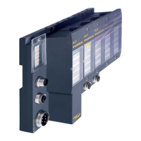
Technology modules
D300529 0115 - BL67 I/O modules12-80
STS_OFLW 0 No overflow
1
Counter value exceeded upper limit of counter range.
STS_ZC 0 No zero crossing
1
Counter value crossed zero value.
REG_WR_AKN 0 No change in the in the registers
→ No command for data change in the registers by the pro-
cess output.
A write access (REG_WR) to the register bank is only possible
when this bit was previously zero; handshake for data transfer
to the registers.
1
Register contents updated
→ A change in the register contents has been instructed by
one process output.
REG_WR_ACCEPT 0 REG_WR_ADR error
→ During REG_WR = 1 the register addressed in REG_WR_ADR
in the control interface could
not successfully be written with
user data.
1
REG_WR_ADR valid
→ During REG_WR = 1 the register addressed in REG_WR_ADR
in the control interface could successfully be written with user
data.
REG_ACT_RD_ADR 0 to 127 Address of the actually read input register.
REG_RD_ABORT 0 REG_RD_ADR valid
→ Reading the register defined in REG_RD_ADR accepted and
carried out. The register content is shown in the user data area
(REG_RD_DATA, byte 0-3).
1
REG_RD_ADR error
→ Reading of the register defined in REG_RD_ADR has not
been accepted. The user data range (REG_RD_DATA, bytes 0-3)
is zero.
REG_RD_DATA 0 to
2
32
-1
Content of the register selected by REG_RD_ADR. If RD_ABORT
= 0, if not REG_RD_DATA = 0.
AUX_RD_DATA 0 to
2
32
-1
Content of the register which has been defined via parameter
byte 14 (see Module parameters).
Table 12-8:
Process input data
of the module
Bit Value Meaning

 Loading...