February 2013
4-139
ColorQube® 9303 Family
REP 12.14-171, REP 12.15-171
Repairs/Adjustments
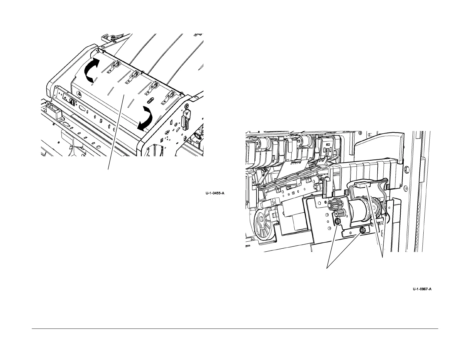
7. Figure 3. Remove the upper exit guide.
Figure 3 Upper exit guide removal.
Replacement
The replacement procedure is the reverse of the removal procedure.
REP 12.15-171 HVF Rear Tamper Assembly
Parts List on PL 12.110.
Removal
WARNING
Take care during this procedure. Sharp edges may be present that can cause injury.
WARNING
Switch off the electricity to the machine. Refer to GP 14. Disconnect the power cord
from the customer supply while performing tasks that do not need electricity. Electricity
can cause death or injury. Moving parts can cause injury.
1. Remove the rear cover REP 12.1-171.
2. Remove the right side-cover REP 12.5-171.
3. Remove the ejector assembly REP 12.6-171.
4. Remove the front tamper assembly, REP 12.11-171.
5. Remove the pressing and support motor, Figure 1.
Figure 1 Motor removal
1
Twist the upper exit guide
and lift upwards.
1
Remove 2 screws.
2
Disconnect the motor an
encoder harness.
 Loading...


