February 2013
4-282
ColorQube® 9303 Family
REP 75.10
Repairs/Adjustments
REP 75.10Tray 5 Elevator Rack Assembly
Parts List on PL 75.68
Removal
WARNING
Switch off the electricity to the machine. Refer to GP 14. Disconnect the power cord
from the customer supply while performing tasks that do not need electricity. Electricity
can cause death or injury. Moving parts can cause injury.
WARNING
Take care during this procedure. Sharp edges may be present can cause injury.
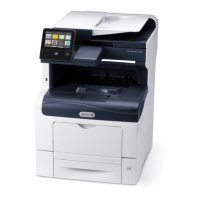
1. Release the cable clamp from the rear cover, Figure 1.
Figure 1 Cable clamp
2. Remove any paper from tray 5, then un-dock the module, REP 75.7.
3. Remove the two front door hinge pins, PL 75.60 Item 3, then remove the front door
assembly, PL 75.60 Item 1.
4. Remove the top, front and rear covers, REP 75.8.
5. Remove the elevator motor assembly, REP 75.4.
6. Remove the frame top brace, PL 75.68 Item 3.
7. Remove the crash bar, PL 75.68 Item 2.
8. Disconnect the transport motor, PL 81.40 Item 2.
9. Disconnect the feed motor, PL 81.40 Item 3.
10. Remove the upper feeder assembly, PL 81.40 Item 1, refer to REP 82.7.
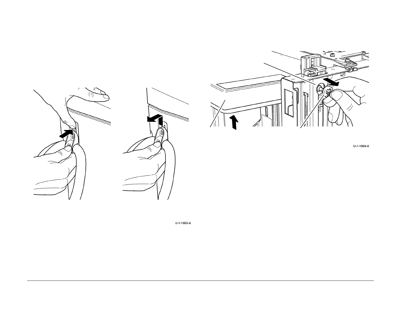
11. Prepare to remove the tray assembly, Figure 2 and Figure 3.
Figure 2 Tray assembly front view
1
Press the locking clip towards the
module.
2
Slide the cable clamp off the
module, in an upwards direction.
aise the tray assembly until the tray level drive
ear clip is in alignment with the access slot of
he frame.
2
Remove the front tray level drive gear
clip from the elevator motor shaft.
Access slot

 Loading...