February 2013
4-151
ColorQube® 9303 Family
REP 12.21-171, REP 12.22-171
Repairs/Adjustments
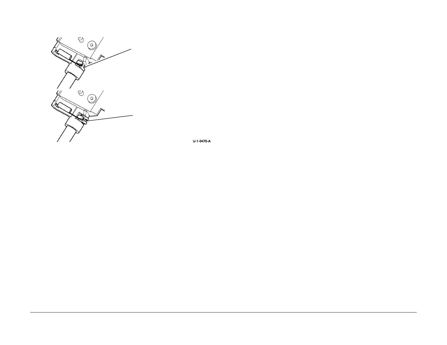
2. When installing the shaft ensure that the anti-play shoe has not moved out of position,
Figure 6.
Figure 6 Location of the anti-play shoe.
3. Ensure that all of the cable ties are installed and that the harnesses are in the correct
position.
4. Check that all of the PJ connections on the BM PWB are connected.
5. Return the allen key to the storage position inside the drive belt tensioner spring, PL
12.160 Item 9.
6. Go to ADJ 12.9-171 and complete the adjustments.
REP 12.22-171 BM Entry Roll
Parts List on PL 12.150.
Purpose
This procedure is used to repair the following components:
• BM entry roll pulley, PL 12.150 Item 14.
• BM entry roll, PL 12.150 Item 15.
Removal
WARNING
Take care during this procedure. Sharp edges may be present that can cause injury.
WARNING
Switch off the electricity to the machine GP 14. Disconnect the power cord from the cus-
tomer supply while performing tasks that do not need electricity. Electricity can cause
death or injury. Moving parts can cause injury.
1. Open the HVF BM front door and fully pull out the BM module.
2. Remove the crease blade knob (6d), PL 12.150 Item 4.
3. Remove the crease roll handle (6c), PL 12.150 Item 5.
4. Remove the BM front cover, PL 12.150 Item 3.
Correct position of the anti-play
shoe.
Ensure that the shaft is gripped
securely.
Incorrect position of the anti-play
shoe.

 Loading...