February 2013
6-23
ColorQube® 9303 Family
GP 7
General Procedures/Information
GP 7 System Grounding Verification
Purpose
Use this procedure to verify correct system grounding
Procedure
WARNING
Do not switch on the electricity to the machine while a ground circuit is disconnected.
Ground circuits ensure that the machine remains safe during a fault condition.
NOTE: Ground distribution faults must be isolated by continuity checks and visual inspection.
Check all circuits between each connection and ground. When appropriate, insert the meter
probe tip into the head of the screw.
• Switch off the machine, GP 14. Disconnect the main power cord from the wall outlet and
the machine. Check the ground conductor of the main power cord for continuity or dam
-
age, if necessary install a new main power cord, PL 1.15 Item 1.
• Check that the ground connections that follow are secure:
– Stripper system
– Transfix
– Registration / Preheat assembly
– Marking Unit
– Drum
– Horizontal Paper Path
– Exit transport
– DADH
– Tray 5
– Bypass Tray
– 3 Tray Module
Stripper system
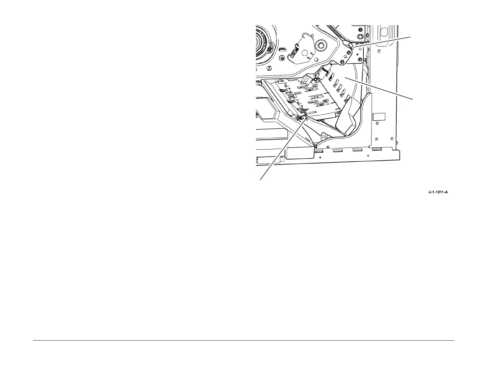
• Figure 1, stripper hinge shafts and stripper baffle. Check for continuity of less than 10
Ohms between the shaft and the machine base with the baffle closed and latched. Check
for continuity of less than 10 Ohms between the baffle and the machine base. To improve
continuity, remove and clean. If necessary, install a new stripper gate and baffle assem
-
bly, REP 10.21, PL 10.12 Item 1.
Figure 1 Stripper baffle
• Figure 2, stripper baffle hinge shaft ground contact spring. Remove the exit module to see
the contact spring. Remove, clean and reform the spring as necessary.
Stripper shaft
Gate and baffle
shaft
Stripper baffle

 Loading...