February 2013
3-46
ColorQube® 9303 Family
IQ 12
Image Quality
IQ 12 Missing or Partial Image RAP
Use this RAP to troubleshoot wide deletions in the process direction that affect a complete
printhead or a when a single colour is missing from a single printhead.
The problem is usually caused by a communication or power error in the marking unit and
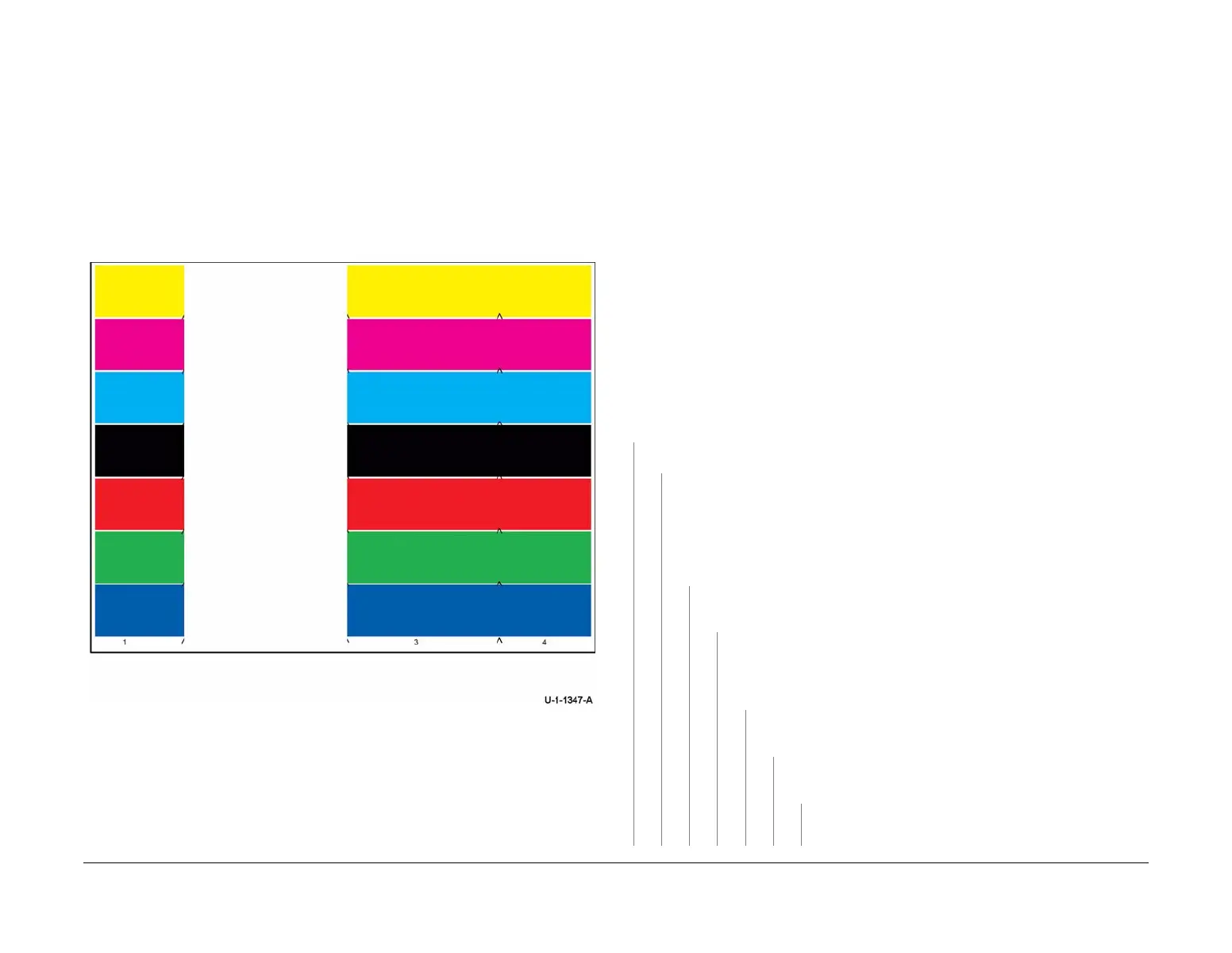
causes the substantial or complete loss of a single printhead, Figure 1 and may be seen in one
or all colours. The problem may be an ink supply problem if only a part of the printhead is miss
-
ing.
NOTE: Blank sheets accompanying multi-feeds or chase pages following a jam are normal.
Ensure IQ 1 Image Quality Entry RAP is performed before starting this RAP.
Figure 1 Printhead 2 failure
Initial Actions
WARNING
Ensure that the electricity to the machine is switched off while performing tasks that do
not need electricity. Refer to GP 14. Disconnect the power cord. Electricity can cause
death or injury. Moving parts can cause injury.
CAUTION
Use care when moving the marking unit into the service position when hot. Ink can spill from
the ink reservoir located at the back of the unit if opened with too much force. Cross-colour ink
contamination could also occur.
CAUTION
The video cable (striped and labeled A, PL 92.10 Item 7) and the wave amp cable (white and
labeled B, PL 92.10 Item 8) should not be interchanged at the printhead connectors. Damage
to the printhead and IME controller PWB will occur if the cables are installed incorrectly.
CAUTION
Do not touch the exposed face of the printheads. Surface contamination or minor damage can
easily make the printhead unusable.
• Check for media or debris around the printhead and drum. Clean as necessary, refer to
GP 27 Cleaning Procedure.
Procedure
Switch off, then switch on the machine, GP 14. Check the PEST fault history, dC123. New
faults are listed in the PEST history.
YN
Print the initial test pages, TP 1. Test pages are good.
YN
NOTE: Before printing TP 26, ensure that A4 or 8.5 x 11 inch plain paper is loaded
long edge feed into tray 4. Use the best quality media available. Do not use hole
punched paper.
Perform dC968 Head Purge on the affected printhead. Print TP 26 Printhead Unifor-
mity / Colour Bands Test Page. Test prints are good.
YN
Reseat the two ribbon cables, PL 92.10 Item 7 and PL 92.10 Item 8, attached to
the affected printhead. Print the initial test pages, TP 1.
The prints are good.
YN
Switch off the machine, GP 14. Swap the two ribbon cables on the
affected printhead with the two ribbon cables on the working printhead on
the same carriage. Switch on the machine, GP 14. Print the initial test
pages, TP 1.
The defect moves to a new location.
YN
Install a new quad wave amp PWB, PL 92.10 Item 3. Print the initial
test pages, TP 1.
The test pages are good.
YN
Install a new IME controller PWB, PL 92.10 Item 1. Print the ini-
tial test pages, TP 1. The test pages are good.
YN
Install a new printhead, PL 91.20 Item 2 or PL 91.25 Item
2.
A B C D E F G

 Loading...