CAMSHAFTS
5-16
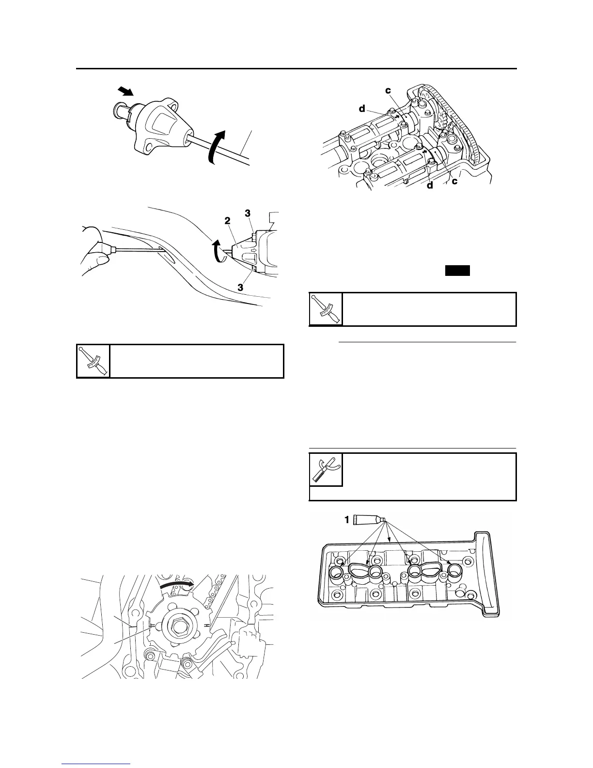
d. Remove the screwdriver, make sure the tim-
ing chain tensioner rod releases, and then
tighten the cap bolt to the specified torque.
▲▲▲▲▲▲▲▲▲ ▲ ▲▲▲▲▲▲▲▲▲ ▲ ▲▲▲▲ ▲ ▲▲▲▲ ▲▲▲
7. Turn:
• Crankshaft
(several turns clockwise)
8. Check:
•“T” mark
Make sure the “T” mark “a” on the pickup ro-
tor is aligned with the crankcase mating sur-
face “b”.
• Camshaft holes
Make sure the holes “c” in the camshafts are
aligned with the arrow marks “d” on the cam-
shaft caps.
Out of alignment → Adjust.
Refer to the installation steps above.
9. Measure:
• Valve clearance
Out of specification → Adjust.
Refer to “ADJUSTING THE VALVE CLEAR-
ANCE” on page 3-3.
10.Install:
• Cylinder head cover gasket
• Cylinder head cover
NOTE:
• Apply Three Bond 1514
®
“1” onto the mating
surfaces of the cylinder head cover and cylin-
der head cover gasket.
• Apply Yamaha bond No.1215 “2” onto the mat-
ing surfaces of the cylinder head cover gasket
and cylinder head.
• Tighten the cylinder head cover bolts in stages
and in a crisscross pattern.
T
R
.
.
Timing chain tensioner cap bolt
6 Nm (0.6 m·kg, 4.3 ft·lb)
1
b
a
T
R
.
.
Cylinder head cover bolt
10 Nm (1.0 m·kg, 7.2 ft·lb)
Yamaha bond No. 1215
90890-85505
(Three Bond No.1215
®
)
New