ELECTRICAL COMPONENTS
8-166
b. Measure the oil level switch resistance.
▲▲▲▲▲▲▲▲▲ ▲ ▲▲▲▲▲▲▲▲▲ ▲ ▲▲▲▲ ▲ ▲▲▲▲ ▲▲▲
EAS28220
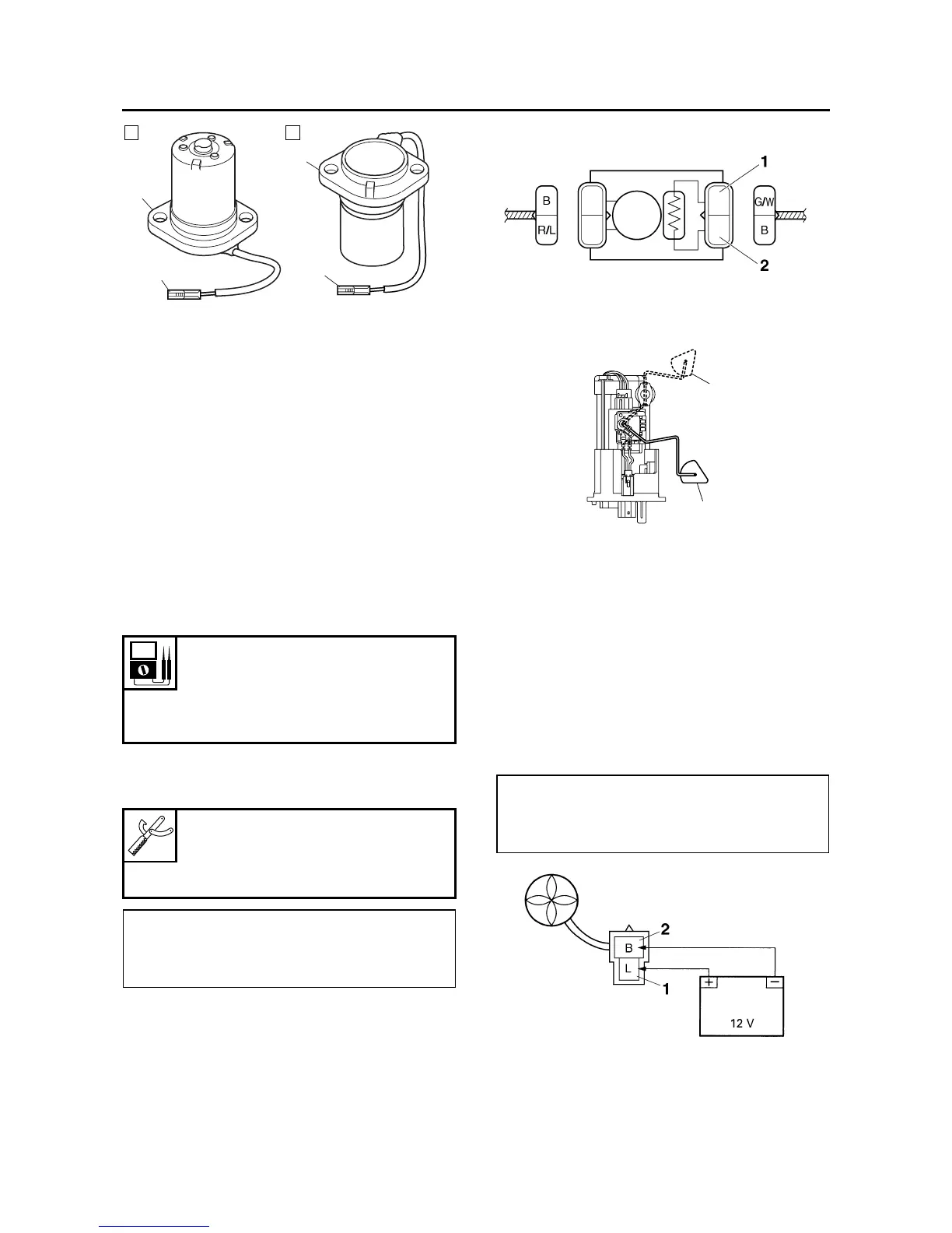
CHECKING THE FUEL SENDER
1. Disconnect:
• Fuel pump coupler
• Fuel sender coupler
(from the wire harness)
2. Remove:
• Fuel tank
3. Remove:
• Fuel pump
(from the fuel tank)
4. Check:
• Fuel sender resistance
Out of specification → Replace the fuel pump
assembly.
▼▼▼▼▼▼▼▼▼ ▼ ▼▼▼▼▼▼▼▼▼ ▼ ▼▼▼▼ ▼ ▼▼▼▼ ▼▼▼
a. Connect the pocket tester (Ω × 10) to the fuel
sender terminals as shown.
b. Move the fuel sender float to minimum “3”
and maximum “4” level position.
c. Measure the fuel sender resistance.
▲▲▲▲▲▲▲▲▲ ▲ ▲▲▲▲ ▲ ▲▲▲▲ ▲ ▲▲▲▲ ▲ ▲▲▲▲ ▲▲▲
EAS28250
CHECKING THE RADIATOR FAN MOTORS
The following procedure applies to both of the
radiator fan motors.
1. Check:
• Radiator fan motor
Faulty/rough movement → Replace.
▼▼▼▼▼▼▼▼▼ ▼ ▼▼▼▼ ▼ ▼▼▼▼ ▼ ▼▼▼▼ ▼ ▼▼▼▼ ▼▼▼
a. Disconnect the radiator fan motor coupler
from the wire harness.
b. Connect the battery (DC 12 V) as shown.
c. Measure the radiator fan motor movement.
▲▲▲▲▲▲▲▲▲ ▲ ▲▲▲▲ ▲ ▲▲▲▲ ▲ ▲▲▲▲ ▲ ▲▲▲▲ ▲▲▲
Fuel sender
Sender unit resistance (full)
19.0–21.0 Ω
Sender unit resistance (empty)
139.0–141.0 Ω
Pocket tester
90890-03112
Analog pocket tester
YU-03112-C
• Positive tester probe →
green/white “1”
• Negative tester probe →
black “2”
1
1
2
2
A
B
• Positive battery terminal →
blue “1”
• Negative battery terminal →
black “2”
4
3