CYLINDER HEADS
ENG
CYLINDER HEAD
REMOVAL
Rear cylinder head
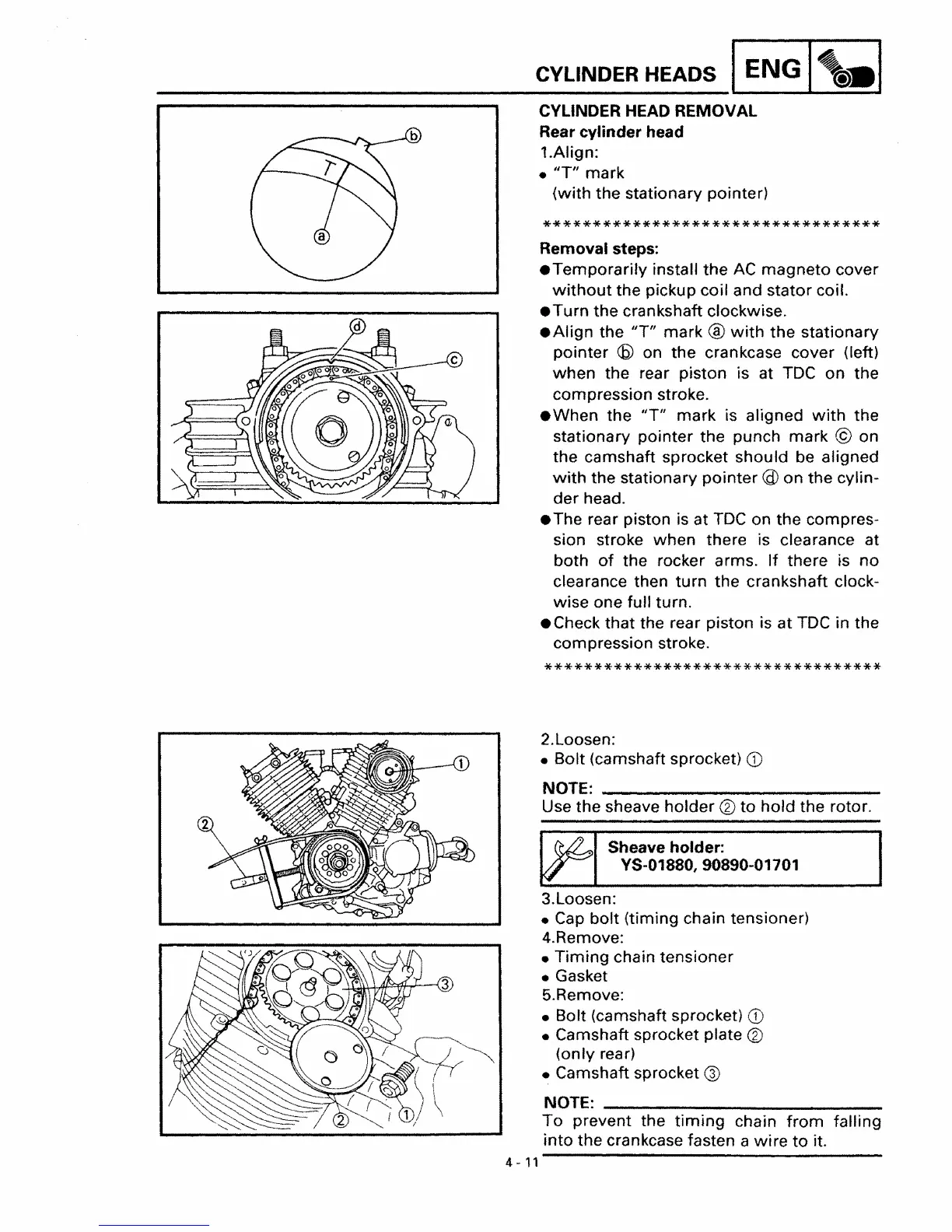
1.Align:
•
"T"
mark
(with the stationary pointer)
**********************************
Removal steps:
.Temporarily
install
the
AC
magneto
cover
without
the pickup coil and stator coil.
• Turn the crankshaft clockwise.
• Align the
liT"
mark ®
with
the
stationary
pointer
(6)
on
the
crankcase cover (left)
when
the rear piston is at TDC on the
compression stroke.
• When
the
"Til
mark
is aligned
with
the
stationary pointer the punch
mark
© on
the camshaft sprocket should be aligned
with
the stationary
pointer
@ on
the
cylin-
der
head.
• The rear piston is at
TDC
on the compres-
sion stroke when there is clearance at
both
of
the rocker arms.
If
there is
no
clearance then
turn
the
crankshaft clock-
wise one full turn.
• Check that the rear piston is
at
TDC
in the
compression stroke.
**********************************
2.Loosen:
• Bolt (camshaft sprocket)
CD
NOTE: _
Use the sheave
holder
®
to
hold
the rotor.
'.
Sheave holder:
YS-01880,90890-01701
3.Loosen:
•
Cap
bolt
(timing chain tensioner)
4.Remove:
•
Timing
chain tensioner
• Gasket
5.Remove:
• Bolt (camshaft sprocket)
CD
• Camshaft sprocket plate ®
(only
rear)
• Camshaft sprocket
®
NOTE:
To
prevent the
timing
chain
from
falling
into
the crankcase fasten a
wire
to
it.
4 -
11