CRANKSHAFT
AND
CONNECTING RODS
ENG
5.1nspect:
• Crank pin surfaces
• Bearing surfaces
Wear/scratches
~
Replace.
6.lnspect:
• Timing chain sprockets
CD
Damage/wear
~
Replace the crankshaft.
7.Measure:
• Oil clearance (crank pin)
Out
of
specification
~
Replace the bear-
ing.
Oil clearance (crank pin):
0.026
....
0.050
mm
(0.001
....
0.002 in)
**********************************
Measurement steps:
Do
not
interchange
the
bearings and con-
necting rods. To obtain
the
correct
oil
clearance and
to
prevent engine damage
they
must
be installed in
their
original posi-
tions
.
• Clean the bearings, crank pins and bear-
ing portions
of
the connecting rods.
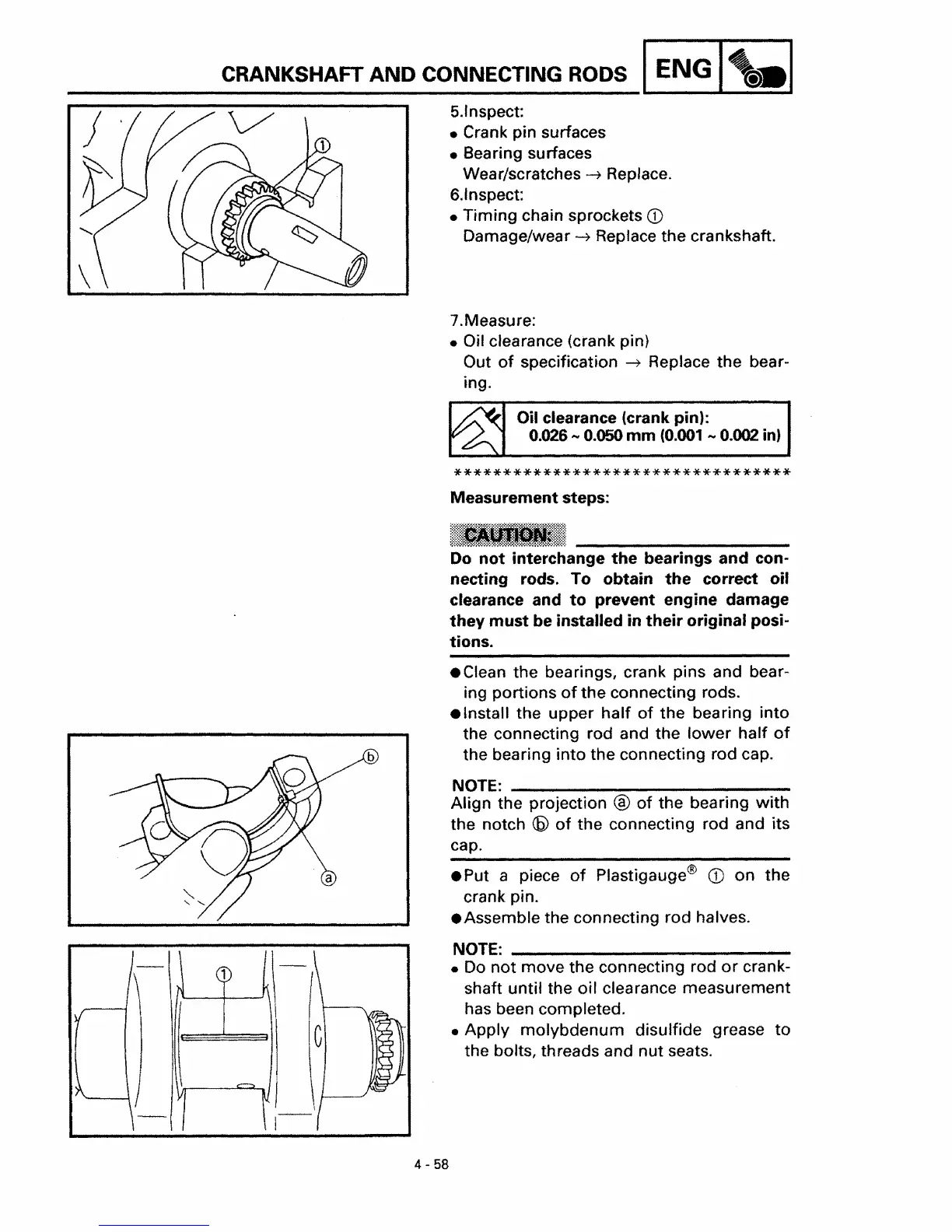
• Install the upper
half
of
the bearing into
the connecting rod and the
lower
half
of
b the bearing into the connecting rod cap.
NOTE: _
Align the projection ®
of
the bearing
with
the notch
(6)
of
the connecting rod and its
cap.
• Put a piece
of
Plastigauge®
CD
on the
crank pin.
• Assemble the connecting rod halves.
NOTE: _
•
Do
not
move the connecting rod
or
crank-
shaft
until the oil clearance measurement
has been completed.
• Apply molybdenum disulfide grease
to
the bolts, threads and nut seats.
4 - 58
 Loading...