CRANKSHAFT
AND
CONNECTING RODS
ENG
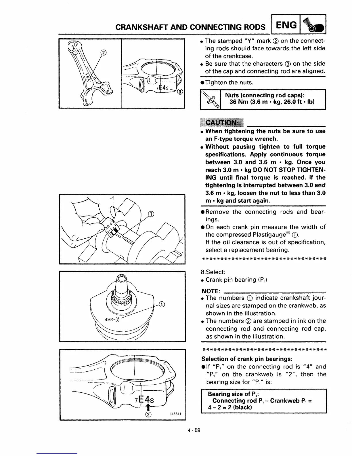
• The stamped
"V"
mark ® on
the
connect-
ing rods should face towards the left side
of
the
crankcase.
•
Be
sure that the characters ® on the side
of
the
cap and connecting rod are aligned.
• Tighten the nuts.
Nuts
(connecting rod caps):
36
Nm
(3.6 m • kg, 26.0
ft
• Ib)
• When
tightening
the
nuts
be sure
to
use
an F-type
torque
wrench.
•
Without
pausing
tighten
to
full
torque
specifications.
Apply
continuous
torque
between 3.0 and 3.6 m • kg. Once
you
reach 3.0 m • kg
DO
NOT STOP TIGHTEN·
ING
until
final
torque
is reached.
If
the
tightening
is
interrupted
between
3.0
and
3.6 m • kg, loosen
the
nut
to
less
than
3.0
m •
kg
and
start
again.
• Remove the connecting rods and bear-
ings.
•
On
each crank pin measure the
width
of
the compressed Plastigauge@
(1).
If
the oil clearance is
out
of
specification,
select a replacement bearing.
**********************************
8.Select:
• Crank pin bearing
(P,)
NOTE: _
• The numbers
CD
indicate crankshaft
jour-
nal sizes are stamped on the crankweb,
as
shown in the illustration.
• The numbers
® are stamped in ink on the
connecting rod and connecting rod cap,
as
shown in the illustration.
**********************************
Selection
of
crank
pin
bearings:
.If
"P," on the connecting rod is
"4"
and
JlP,"
on the crankweb is
1/2"
f then the
bearing size
for
IlP,fJ
is:
Bearing size
of
P,:
Connecting rod
P,
- Crankweb
P,
=
4 - 2 =2 (black)
®
145341
4 - 59
 Loading...