**********************************
Ring gear
thrust
washer
clearance mea-
surement
steps:
• Remove the ring gear assembly.
• Place
four
pieces
of
Plastigauge®
between the
originally
installed ring gear
thrust
washer and the ring gear.
• Install the ring gear assembly
and
tighten
the bolts
to
specification.
Bolt
(bearing housing):
23
Nm
(2.3 m • kg, 16.6
ft
• Ib)
NOTE:
When using Plastigauge®
to
measure the
ring gear
thrust
washer clearance do
not
turn the shaft drive and ring gear.
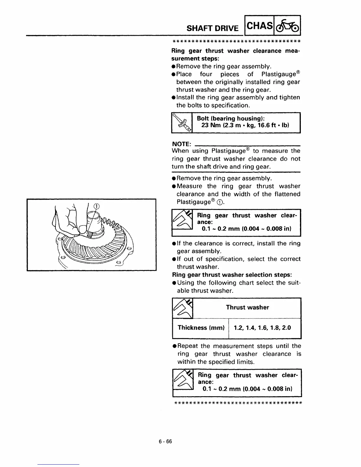
• Remove the ring gear assembly.
• Measure the ring gear
thrust
washer
clearance and the
width
of
the
flattened
Plastigauge®
CD.
.If
the clearance is correct, install the ring
gear assembly.
•
If
out
of
specification, select
the
correct
thrust washer.
Ring gear
thrust
washer selection steps:
• Using the
following
chart select the suit-
able thrust washer.
Ring gear
thrust
washer
clear-
ance:
0.1
....
0.2
mm
(0.004
...,
0.008 in)
Thrust
washer
Thickness (mm) 1.2, 1.4, 1.6, 1.8, 2.0
.Repeat
the measurement steps until the
ring gear
thrust
washer clearance is
within
the specified limits.
Ring gear
thrust
washer
clear-
ance:
0.1
....
0.2
mm
(0.004
....
0.008 in)
**********************************
 Loading...