EB80201C
IGNITION SYSTEM I
ELEC
I0 I
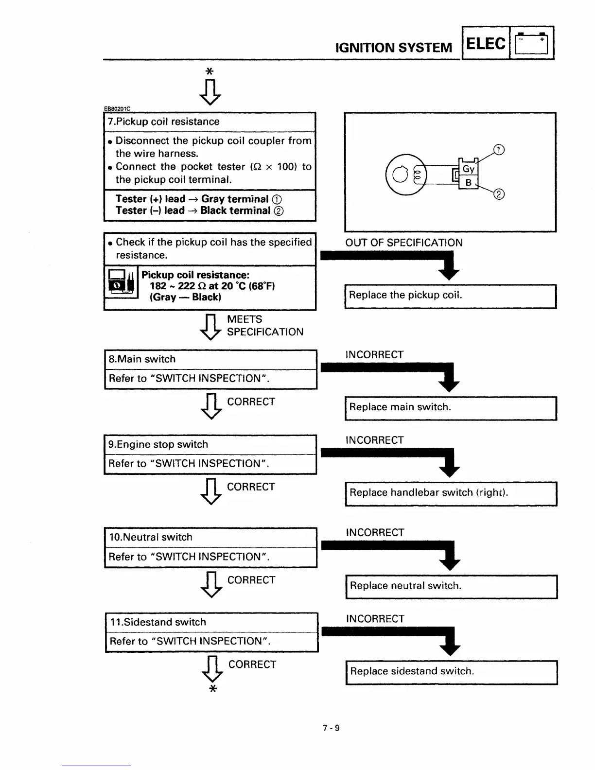
7.Pickup coil resistance
• Disconnect the pickup coil coupler
from
the
wire
harness.
• Connect the pocket tester
(.0 x 100)
to
the pickup coil terminal.
Tester
(+) lead
~
Gray
terminal
<D
Tester (-) lead
~
Black
terminal
®
• Check
if
the pickup coil has the specified
resistance.
~
Pickup coil resistance:
182
....
222 .0
at
20
°C
(68°F)
(Gray - Black)
n MEETS
V SPECIFICATION
8.Main switch
Refer
to
"SWITCH INSPECTION".
~
CORRECT
9.Engine stop switch
Refer
to
iiSWITCH INSPECTION".
~
CORRECT
10.Neutral switch
Refer
to
IiSWITCH INSPECTION
iI
•
~
CORRECT
11.Sidestand switch
Refer
to
IiSWITCH INSPECTION
iI
•
~
CORRECT
*
OUT
OF
SPECIFICATION
l
IReplace the pickup coil.
INCORRECT
IReplace main switch.
INCORRECT
IReplace handlebar switch (right).
INCORRECT
IReplace neutral switch.
INCORRECT
IReplace sidestand switch.
7-9