Control Constants
10-4
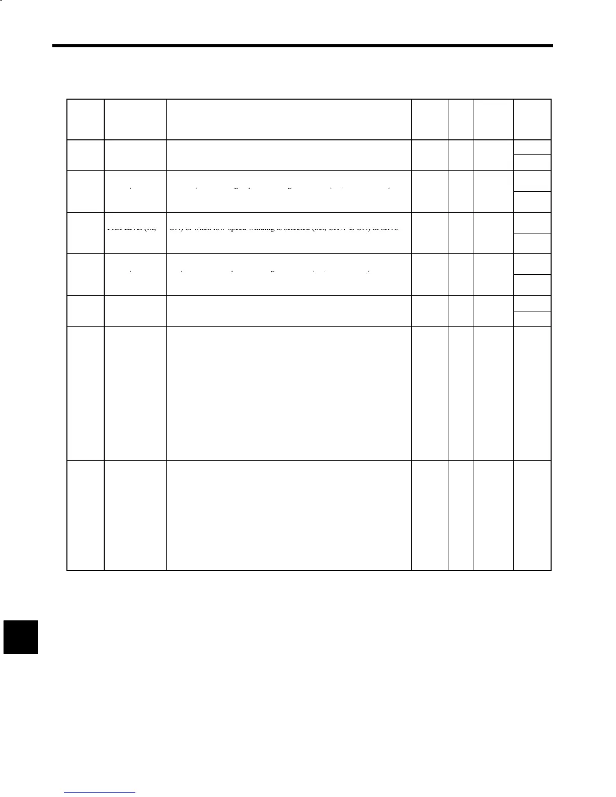
Table 10.1 User Constants (continued)
Con-
stant
No.
Name Explanation Change
*
1
Unit Standard
Setting
Upper
Limit/
Lower
Limit
Servo Mode
Motor flux level when high-speed gear is selected (i.e., MGR and LGR
100
C1-31
F
ux Leve
H
φ
SVH
are OFF
or w
en
g
-spee
w
n
ng
sse
ecte
.e., CHW
s OFF
n
servo mode (i.e., SV is OFF).
No % 70
30
Servo Mode
Base Speed Ra-
Base speed ratio when high-speed gear is selected (i.e., MGR and LGR
are OFF) or when high-speed winding is selected (i.e., CHW is OFF) in
5.00
C1-32
tio (H)
R
BSH
servo mode (i.e., SV is ON).
Base speed (Servo) = R
BSH
× Base speed (Motor)
No --- 1.00
1.00
Servo Mode
Flux Level (M,
Motor flux level when low-speed gear is selected (i.e., MGR or LGR is
ON) or when low-speed winding is selected (i.e., CHW is ON) in servo
100
C1-33
L)
φ
SVL
mode (i.e., SV is ON).
No % 70
30
Servo Mode
Base Speed Ra-
Base speed ratio when low-speed gear is selected (i.e., MGR or LGR is
ON) or when low-speed winding is selected (i.e., CHW is ON) in servo
5.00
C1-34
tio (M, L)
R
BSL
mode (i.e., SV is ON).
Base speed (Servo) = R
BSL
× Base speed (Motor)
No --- 1.00
1.00
Zero-speed
Time for generating braking force after deceleration and zero-speed is
100
C1-35
Bra
ng T
me
T
BLK
reac
e
to stop.
No sec 0
0
C1-36
Signal Selec-
tions 1
SEL1
*
4
Selections for multi-functional signals and other selections.
*
3
S Bits 1 and 0: 6CN pin 11
00: TLL 01: −−−
10: INC 11: −−−
S Bit 2: 6CN pin 10
0: TLH 1: −−−
S Bit 3: 6CN pin 12
0: SSC 1: SV
S Bit 4: 6CN pin 15
*
2
0: PPI 1: LM10
S Bit 7: 1CN 12-bit digital reference signal selection
*
2
0: Digital speed reference
1: Orientation control stop position reference
No --- 00000000 ---
C1-37
Signal Selec-
tions 2
SEL2
*
4
Selections for multi-functional signals and other selections.
*
3
S Bits 1 and 0: RUN mode selection
00: Operation by speed reference
11: Operation by Digital Operator
S Bit 2: 6CN pin 6
0: RDY 1: EMG2
S Bits 7 and 6: Digital speed reference selection
*
2
00: 2-digit BCD
01: 12-bit binary
10: 3-digit BCD
11: Internal speed setting
No --- 01000000 ---
10
 Loading...


