Control Constants
10-6
Con-
stant
No.
Upper
Limit/
Lower
Limit
Standard
Setting
UnitChange
*
1
ExplanationName
C1-41
Internal Speed
Reference Set
Values
Set values when using internal speed references using digital speed refer-
ences. The correspondence with reference inputs (1CN) are as shown
below, and are given as percentages over the rated speed (C1-26).
100.00
to
C1-48
*
2
o
Pin 19: SPD1 Pin 23: SPD5
Pin 20: SPD2 Pin 24: SPD6
Pin 21: SPD3 Pin 25: SPD7
Pin 22: SPD4 Pin 26: SPD8
No % 0.00
0.00
C1-49
Servo Mode
Speed Refer-
ence Gain
SVGAIN1 and
Set value of the analog speed reference read gain in servo mode. (En-
abled when C1-38 bit 3 is ON and C1-40 bit 5 is ON.) Set the ratio of the
number of rotations when the analog speed reference is 10 V over the
rated speed (C1-26).
100.00
to
C1-50
*
2
Analog speed reference 10 V/(S100 x SVGAIN/100) min
−1
.
Select C1-49 and C1-50 using the DAS signal (C6N-5).
DAS = OFF: C1-49 (SVGAIN1)
DAS = ON: C1-50 (SVGAIN2)
No % 100.00
0.00
C1-51
to
C1-53
--- ---
--- --- --- ---
*
Speedmeter Sig-
nal Offset Ad-
Offset adjustment value for speedometer signal. Outputs speedometer
signal after subtracting from SM
OFS.
5.4
200
C1-54
justment Value
SM
OFS
.
Yes
.
mV
0
−200
*
Load Meter Sig-
nal Offset Ad-
Offset adjustment value for load meter signal. Outputs speedometer
signal after subtracting from LM
OFS.
5.4
200
C1-55
justment Value
LM
OFS
.
Yes
.
mV
0
−200
C1-56
Inverter Capac-
ity Selection
UNITNO
Inverter capacity setting. (The setting is already made at factory prior
to shipment.)
404545P5
25
47P5
26
4011
27
4018
4022
4030
2B
4037
2C
4015
28
29 2A 2D
2037
CIMR
−M5
23P7
04
25P5
05
27P5
06
2015 2018 2022
0A
2030
0B
2011
07 08 09 0C
CIMR
−M5
When the setting has changed, turn the control power supply OFF for
3 seconds or longer then ON again.
200 V class
400 V class
Set value
Set value
No --- --- ---
C1-57
Signal Selec-
tions 6
SEL6
*
4
Control mode signal selections
S Bit 0: Fault record clear selection
0: Disabled
1: Clears next time control power is turned ON.
(Automatically returns to 0.)
S Bit 4 and 5: Emergency stop fault (AL-21) detection time selection
*
5
00: 10 sec
01: 20 sec
10: 40 sec
11: Disabled
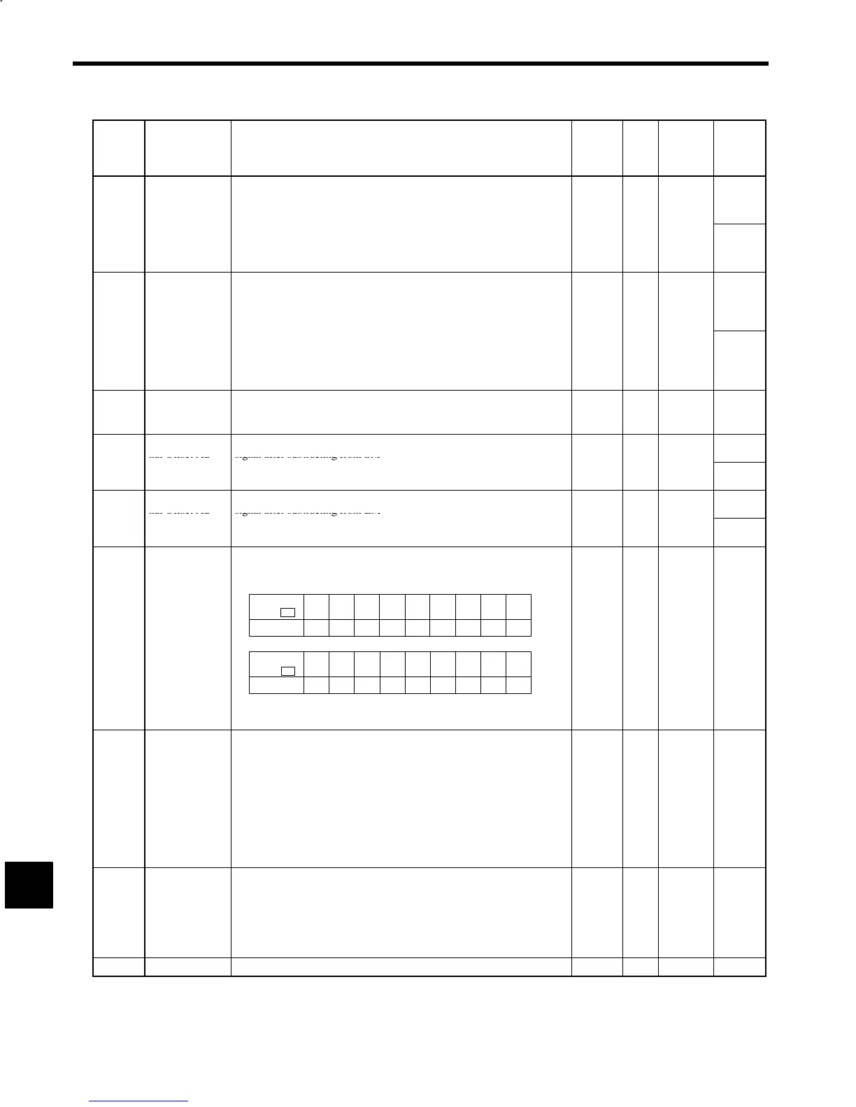
No --- 00000000 ---
C1-58
Signal Selec-
tions 7
SEL7
*
4
Control mode signal selections
S Bit 0: YENET1200 card encoder selection
0: Motor encoder (2CN)
1: Load shaft encoder (8CN)
When the setting has changed, turn the control power supply OFF then
ON again.
No --- 00000000 ---
C1-59
--- --- --- --- --- ---
10
 Loading...


