10.1 User Constants
10-7
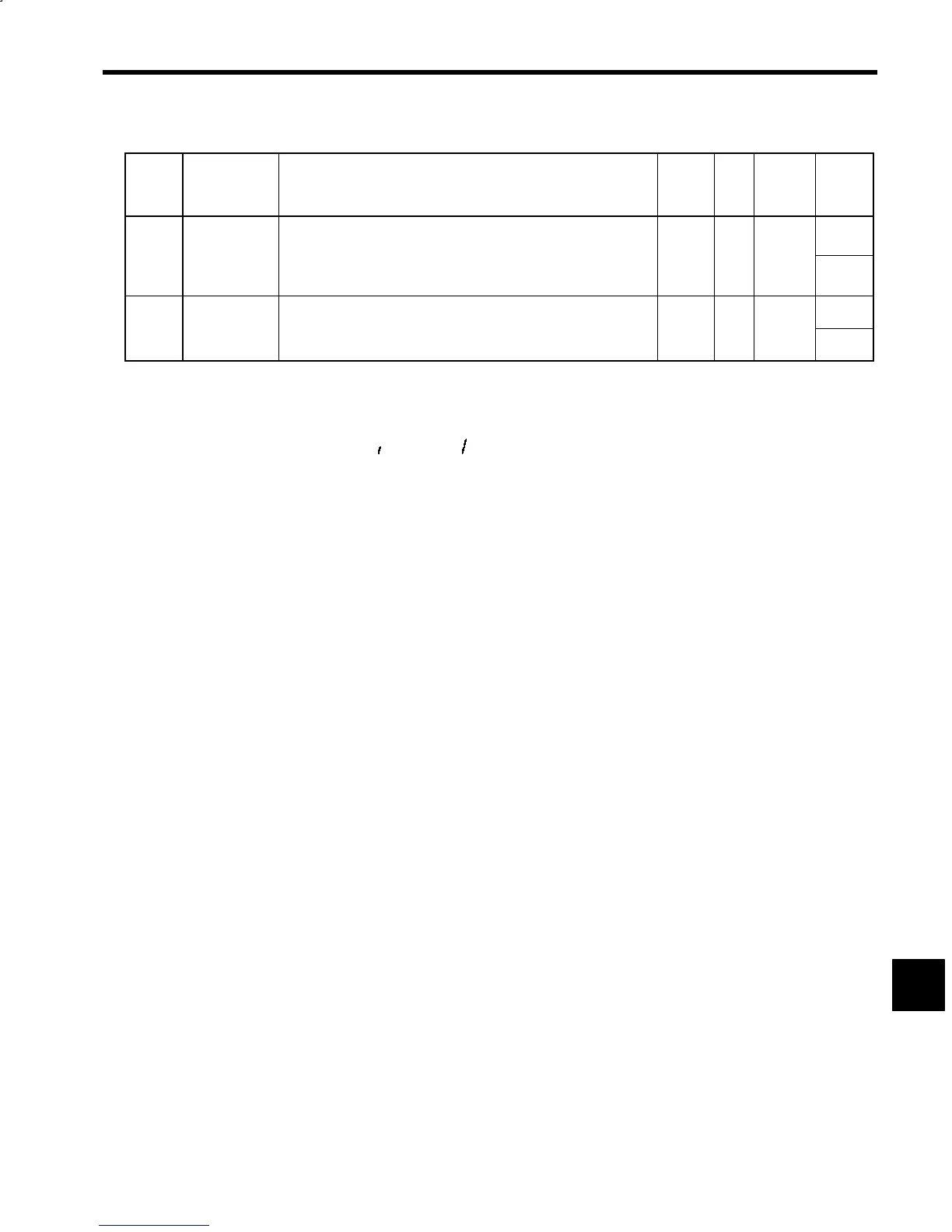
Table 10.1 User Constants (continued)
Con-
stant
No.
Name Explanation Change
*
1
Unit Standard
Setting
Upper
Limit/
Lower
Limit
Magnetic Pole
Positioning
*
Adjusts the position of the magnetic pole. Sets the difference between the
magnetic position and the encoder origin signal using the electrical angle
_
=
-
8191
C1-60
Value
=
.
-
v
u
x.
When the setting has changed, turn the control power supply OFF then
ON again.
No --- 4096
−8192
Phase-C Pulse
Width
*
6
Sets the pulse width of the motor encoder origin signal (phase C). Set the
C1-61 value listed on the terminal box.
100
C1-61
When the setting has changed, turn the control power supply OFF then
ON again.
No Pulse 7
0
*1. Change (change during operation) column: Indicates whether the constant can be changed during inverter operation.
Yes: Constant can be changed during inverter operation; No: Constant cannot be changed during inverter operation
*2. This constant is enabled for stand-alone drives (M5A) only. Do not change the set value for NC system s (M5N).
*3. Connector pin numbers are for stand-alone drives.
*4. In signal selection descriptions, 0 stands for “
” and 1 for “ .”
*5. This function is available in the following software.
VSM200XXX: VSM200112 or later
*6. Constants only for IPM motors (with syncs using flush-type permanent magnets). C1-60 and C1-61 are not displayed when the
software for controlling an induction motor is used.
10
 Loading...


