14.1 Drives
14 -13
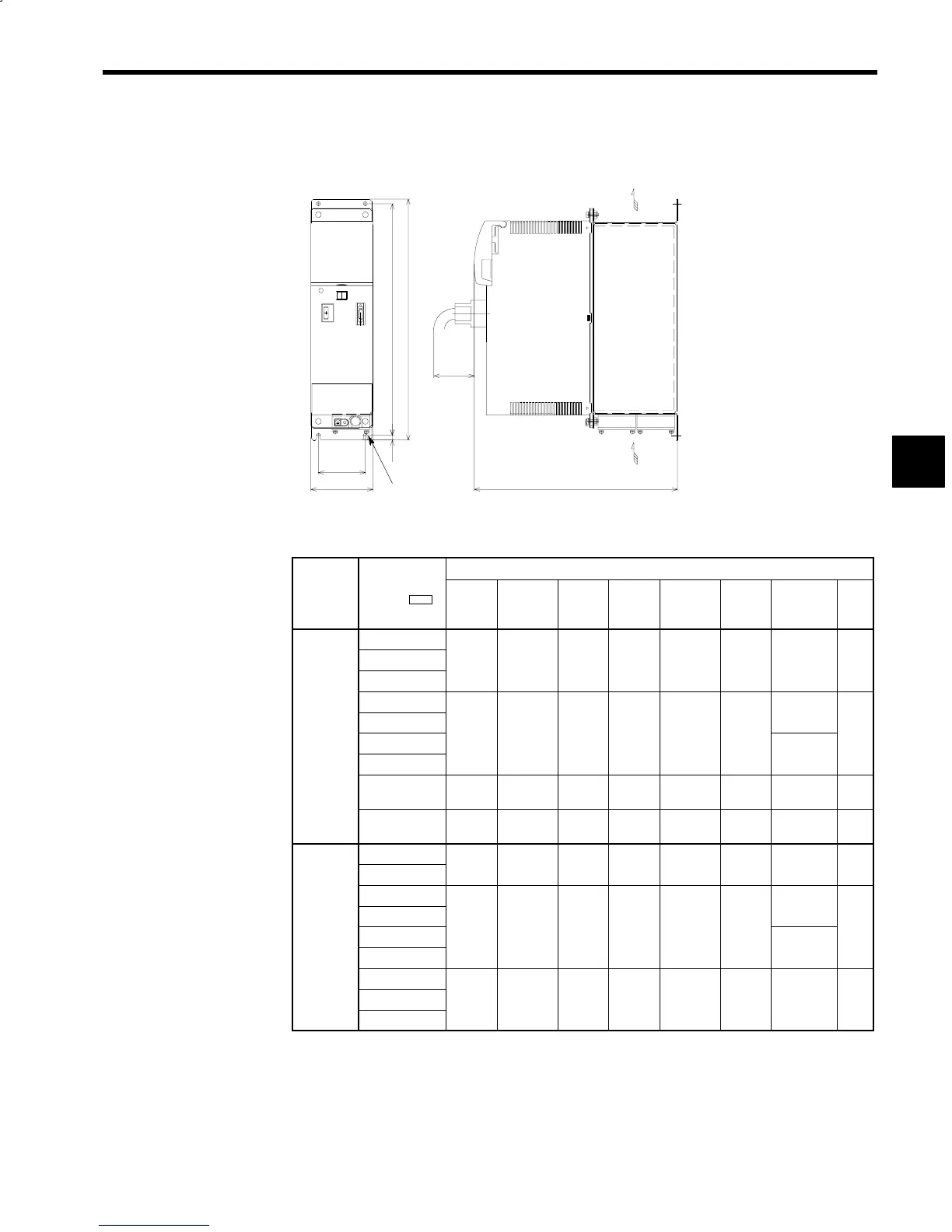
J Converter (VS-656MR5) Open Chassis Type
The figures below show a 200 V 10 HP (7.5 kW) model.
D
H
H1H2
4-d
W1
W
Max.70mm
(2.76 inches)
Air
Air
Fig 14.4 Dimensions of the Converter
Table 14.8 VS-656MR5 Dimensions and Approx. Mass
External Heatsink Cooling Type Dimensions in mm (inches)
Voltage
Class
Model CIMR-
MR5j*
W H D W1 H1 H2 Approx.
Mass
kg (Ib)
d
23P7
25P5
100
3.94
385
15.16
324
12.76
75
2.95
370
14.57
7.5
0.30
6
13
M5
.
.
.
.
.
.
27P5
2011
16
2015
150 470 324 100 455 6.5
(35)
5.91
18.5
12.76
3.94
17.91
.
0.26
M5
c
ass
2018
.
.
.
.
.
.
16.5
2022
.
(36)
2030
200
(7.87)
470
(18.5)
324
(12.76)
150
(5.91)
455
(17.91)
6.5
(0.26)
21.5
(47)
M5
2037
300
(11.81)
470
(18.50)
324
(12.76)
250
(9.84)
455
(17.91)
7
(0.28)
40
(1.57)
M6
45P5
100 385 324 75 370 7.5 8
3.94
15.16
12.76
2.95
14.57
.
0.30
18
M5
47P5
.
.
.
.
.
.
4011
16
4015
150 470 324 100 455 6.5
(35)
400 V
5.91
18.5
12.76
3.94
17.91
.
0.26
M5
4018
.
.
.
.
.
.
16.5
4022
.
(36)
4030
4037
250
9.84
470
18.50
324
12.76
200
7.87
455
17.91
7
0.28
30
0.98
M6
.
.
.
.
.
.
.
4045
Note: The 2037 and 4030 to 4045 models are in development.
* A: For stand-alone drive system N: for NC system
14
 Loading...


