3.3 Wiring Main Circuit Terminals
3-9
2. If ambient temperature exceeds 30°C (86°
F
), the allowable current of wire may be lowered.
3. Temperature for each wire indicates the maximum allowable conductor temperature.
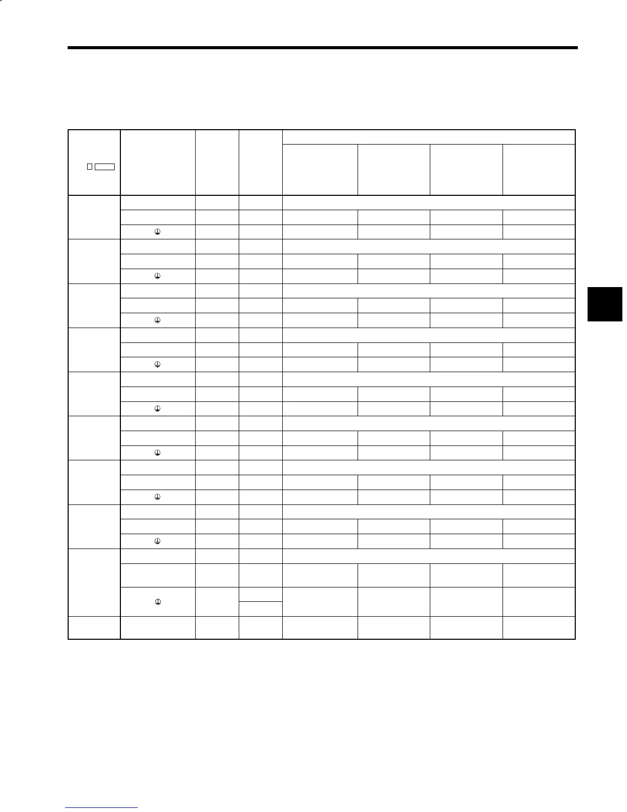
Table 3.3 200 V Class Inverter Power Cable Specifications
Wire Sizes
Model CIMR-
M5
Terminal Symbols
Terminal
Screw
Tighten-
ing
Torque
(N S m)
UL-approved
75°C (167°F)
Temperature-rated
Copper Wire
[AWG (mm
2
)]
600 V Vinyl-
sheath Insulated
Wire (IV, VV)
60°C (140°F)
(mm
2
)
600 V Cross-
linked Polyethy-
lene Wire (IC)
90°C (194°F)
(mm
2
)
600 V Rubber-in-
sulated Cabtyre
Cable (CT)
60°C (140°F)
(mm
2
)
P/¨,N/© M6 2.94 (*1)
23P7
U/T1, V/T2, W/T3 M5 2.35 8 (8.4) 5.5 3.5 5.5
M5 × 2 2.35 10 (5.3) 3.5 2 3.5
P/¨,N/© M6 2.94 (*1)
25P5
U/T1, V/T2, W/T3 M5 2.35 8 (8.4) 5.5 3.5 5.5
M5 × 2 2.35 10 (5.3) 3.5 2 3.5
P/¨,N/© M6 2.94 (*1)
27P5
U/T1, V/T2, W/T3 M5 2.35 8 (8.4) 8 3.5 8
M5 × 2 2.35 8 (8.4) 5.5 3.5 5.5
P/¨,N/© M6 × 2 2.94 (*1)
2011
U/T1, V/T2, W/T3 M8 6.47 6 (13.3) 14 8 14
M6 × 2 3.4 to 4.9 8 (8.4) 8 5.5 5.5
P/¨,N/© M6 × 2 2.94 (*1)
2015
U/T1, V/T2, W/T3 M8 6.47 4 (21.2) 22 14 22
M6 × 2 3.4 to 4.9 6 (13.3) 14 8 8
P/¨,N/© M6 × 2 2.94 (*1)
2018
U/T1, V/T2, W/T3 M8 6.47 3 (26.7) 30 14 30
M6 × 2 3.4 to 4.9 6 (13.3) 14 8 14
P/¨,N/© M6 × 2 2.94 (*1)
2022
U/T1, V/T2, W/T3 M8 6.47 2 (33.6) 50 22 38
M6 × 2 3.4 to 4.9 6 (13.3) 14 8 14
P/¨,N/© M6 × 2 2.94 (*1)
2030
U/T1, V/T2, W/T3 M8 7.8 to 9.8 2/0 (67.4) 80 38 80
M6 × 2 3.4 to 4.9 4 (21.2) 22 14 14
P/¨,N/© M6 × 4 2.94 (*1)
2037
U/T1, V/T2, W/T3 M10
14.7 to
19.6
3/0 (85.0) 100 50 100
M8 × 2,
7.8 to 9.8
,
M6
3.4 to 4.9
3 (26.7) 22 14 22
2011 to
2037
A12/r2, A22/t2 (*2) M4 1.2 to 2.0 14 (2.1) 2 2 2
* 1. Connect using exclusive-use connection bus bar.
* 2. Provided for open chassis type with a minimum capacity of 11 kW. Not provided for external heatsink cooling type.
Notes: 1. Wire size is selected assuming external suspended wiring of single 3-core cables at
an ambient temperature of 30°C (86°
F
).
2. If ambient temperature exceeds 30°C (86°
F
), the allowable current of wire may be lowered.
3. Temperature for each wire indicates the maximum allowable conductor temperature.
3