vii
IM 05P02D41-01EN
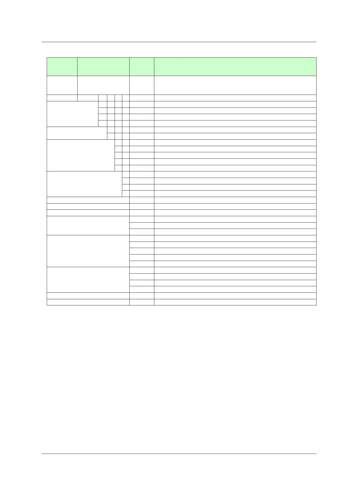
ModelandSuffixCodesofUP35A(forDetailedCodeModel)
Model Suffixcode
Optional
suffix
code
Description
UP35A
Program Controller (provided with 3 DIs, and 3 DOs) (Power supply:
100-240 V AC)
2 program patterns/20 program segments (Max. 20 segments per pattern)
Fixed code -NNN Always “-NNN”
Display language (*1)
-1 English (Default. Can be switched to other language by the setting.)
-2 German (Default. Can be switched to other language by the setting.)
-3 French (Default. Can be switched to other language by the setting.)
-4 Spanish (Default. Can be switched to other language by the setting.)
Case color
0 White (Light gray)
1 Black (Light Charcoal gray)
Output 1 (*2) (*3) (*5)
-A Analog output (current/voltage pulse)
-R Relay output (c-contact)
-U Universal output (current/voltage pulse/relay)
-T Triac output
-P Position proportional output
Output 2 (*2) (*3) (*4) (*5)
A Analog output (current/voltage pulse)
R Relay output (a-contact)
U Universal output (current/voltage pulse/relay)
N None
Additional program pattern /AP 2 additional patterns/20 additional segments
Retransmission output (*4) /RT Retransmission output or 15 V DC power supply
Heater break alarm (*5) /HA Heater break alarm
E1 terminal area (*6)
/X1 5 additional DIs
/Y1 5 additional DOs
/W1 2 additional DIs and 2 additional DOs
E3 terminal area (*6) (*7)
/CH3 RS485 communication (Max. 38.4 kbps, 2-wire/4-wire)
/CC3 CC-Link communication (with Modbus master function)
/PD3 PROFIBUS-DP communication (with Modbus master function)
/DN3 DeviceNet communication (with Modbus master function)
/ET3 Ethernet communication (with serial gateway function)
E4 terminal area (*6) (*7)
/L4 24 V DC loop power supply
/X4 5 additional DIs
/Y4 5 additional DOs
/W4 2 additional DIs and 2 additional DOs
Power supply /DC Power supply 24 V AC/DC
Additional treatment (*8) /CT Coating
*1: English, German, French, and Spanish are available for the guide display.
*2: For heating/cooling output, both Output 1 and Output 2 should be specified. Not available
when Output 2 is “N”. For position proportional output, specify “-P” for Output 1 and “N” for
Output 2.
*3: When the code for Output 1 is "-R" or "-U" and Output 2 is "R" or "U", Output 1 is changed
from the contact point c to the contact point a. When the code for Output 1 is specified to
"-T", only "A" or "N" is available for Output 2.
*4: The /RT option can be specified only when the code for Output 2 is “R” or “N.”
*5: The /HA option can be specified in the combination of Output 1 and Output 2 codes except
for “-PN.”
*6: Only one option is available for each terminal area of E1, E2 and E4.
*7: The /L4 option for E4 terminal area can be specified only when the E3 terminal area option
is not specified or specified /CH3.
*8: When the /CT option is specified, the UP35A does not conform to the safety standards (UL
and CSA) and CE marking (Products with /CT option are not intended for EEA-market).

 Loading...


