16-13
IM 05P02D41-01EN
Troubleshooting, Maintenance, and Inspections
16
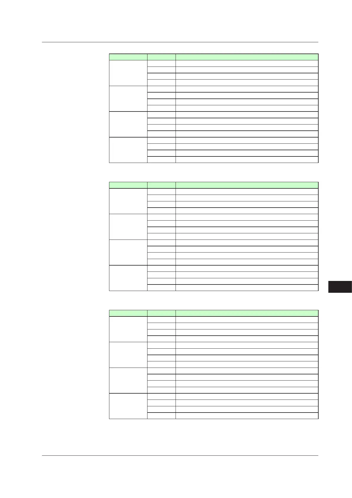
Parameter OP.ER
Displayeddigit bit Description
1st digit 0 Non responding hardware in E1-terminal area
1 –
2 Non responding hardware in E3-terminal area
3 –
2nd digit 4 Non responding hardware in E4-terminal area
5 –
6 –
7 –
3rd digit 8 Communication error in E1-terminal area
9 –
10 Communication error in E3-terminal area
11 –
4th digit 12 –
13 –
14 –
15 –
Parameter AD1.E
Displayeddigit bit Description
1st digit 0 ADC error of PV input
1 –
2 –
3 –
2nd digit 4 –
5 RJC error of PV input
6 –
7 –
3rd digit 8 PV input burnout error
9 –
10 –
11 –
4th digit 12 –
13 –
14 –
15 –
Parameter AD2.E
Displayeddigit bit Description
1st digit 0 Feedback input resistor/current burnout
1 Automaticvalvepositionadjustmenterror
2 –
3 –
2nd digit 4 –
5 –
6 –
7 –
3rd digit 8 –
9 –
10 –
11 –
4th digit 12 –
13 –
14 –
15 –
16.1 Troubleshooting

 Loading...


