17-28
IM 05P02D41-01EN
UP32A
Multiple wiring (multi-drop) of connector
Multiple wiring of the UTAdvanced connector with other devices is possible within
the following multi-wire connection capacity range.
Multi-wire connection capacity (Two wires with the same cross-sectional area)
• Single wire 0.2 to 1.0 mm
2
/twisted wire 0.2 to 1.5 mm
2
• Twisted wire with bar terminal (without plastic sleeve) 0.25 to 1.0 mm
2
• Twisted wire with twin bar terminals (with plastic sleeve) 0.5 to 1.5 mm
2
(Suffix code 3=3)
FG:
Flame ground
SLD:
Shield
DG:
TX/RX signal ground
DB:
RX/TX signal
- signal
DA:
RX/TX signal
+ signal
CHK(red)
(Lit: User profile error/Adress error, Unlit: Normal)
L ERR(red)
(Lit: Communication failure(CRC error), Unlit: Normal)
L RUN(green)
(Lit: Normal, Unlit: No carrier detected/Communication timeout)
Not used
RS-485
RSB(+)
RSA(-)
SG
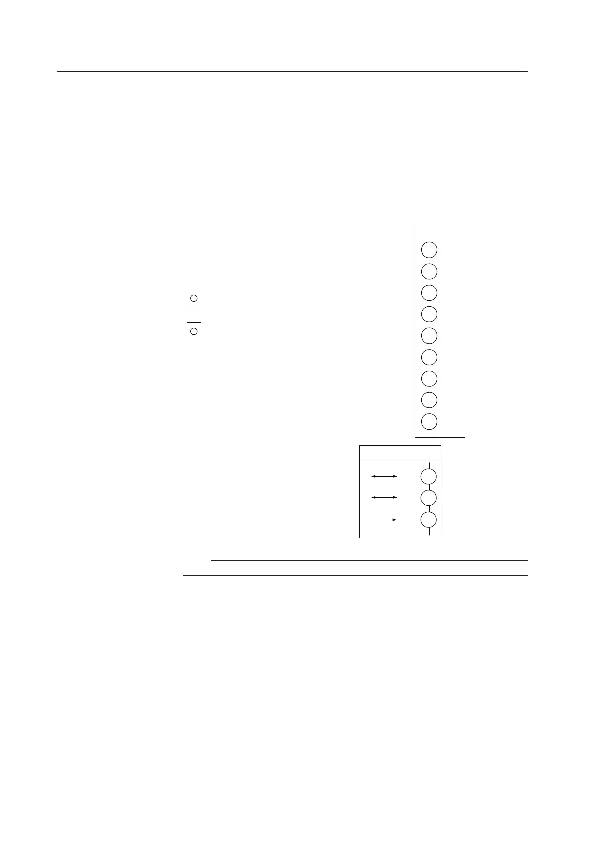
If the UP is located at the end of a
segment for the CC-Link
communication wiring,terminating
resistors are separately needed.
These are to be prepared by users.
(110 Ω: 1 pc.)
DB
DA
110Ω
301
302
303
304
305
306
307
308
309
310
311
312
Up to 32 UTAdvanced series (Modbus/RTU
slave) controllers can be connected.
Note
Use FG as an exclusive ground. Be sure to ground using a low grounding resistance.
Modbusmasterwiring
RS-485 communication wiring for the serial gateway function is as follows.
Up to 32 UTAdvanced series controllers can be connected.
17.4 Wiring

 Loading...


