FaultdiagnosisAlarm
The function outputs an alarm signal in the following cases.
Thecorrespondingevent(EV)lampislitandthecontactoutputturnson(whenthe
contacttypeisenergized).
• BurnoutofPVinput,RSPremoteinput,orauxiliaryanaloginput
• ADC failure ofPVinput,RSPremoteinput,orauxiliaryanaloginput
• Referencejunctioncompensation(RJC)errorofPVinput,RSPremoteinput
The fault diagnosis alarm does not work the stand-by action functions.
FAIL output
When the FAIL condition is caused (faulty MCU or system data error), DO (alarm output)
turned off regardless of contact type.
TheFAILoutput
doesnotworkthealarmlatch,theenergized/de-energizedandthe
stand-by action functions.
Stand-byAction
The stand-by action is a function for ignoring the alarm condition and keeps the alarm off
until the alarm condition is removed. Once the alarm condition is removed, the stand-by
action is cancelled.
It is effective in the following cases where;
•
The power is turned on
• SP is changed
• SP number is switched (however, except for remote setpoint) (The SP must be
changed.)
• The alarm type is changed
• Forced stand-by via communication
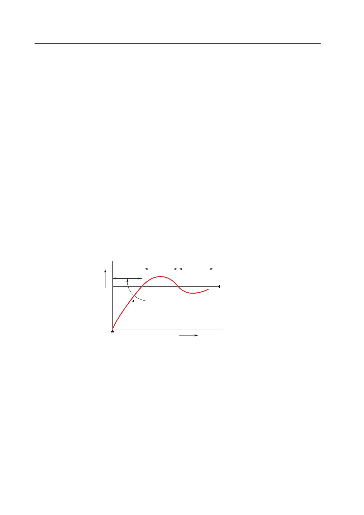
The following shows the behavior of an alarm with the stand-by action at power ON.
Treated
as normal
ºC
Power-on
Time
The alarm output does not turn on
in this region even if the PV valule
is below PV low limit alarm setpoint.
PV low limit alarm setpoint
Normal Abnormal
The alarm output
turns on.
11.1SettingAlarmType

 Loading...
