7-14
IM 05P01C31-01EN
7.3 Using4-wireRTDasPVInput
Description
To use the 4-wire RTD, the optional suffix code /DR is required for remote input (UT55A
suffixcode:T
ype2=1,2,4,5,or7;UT52Asuffixcode:Type2=1or2),ortheoptional
suffix code /U1 is required.
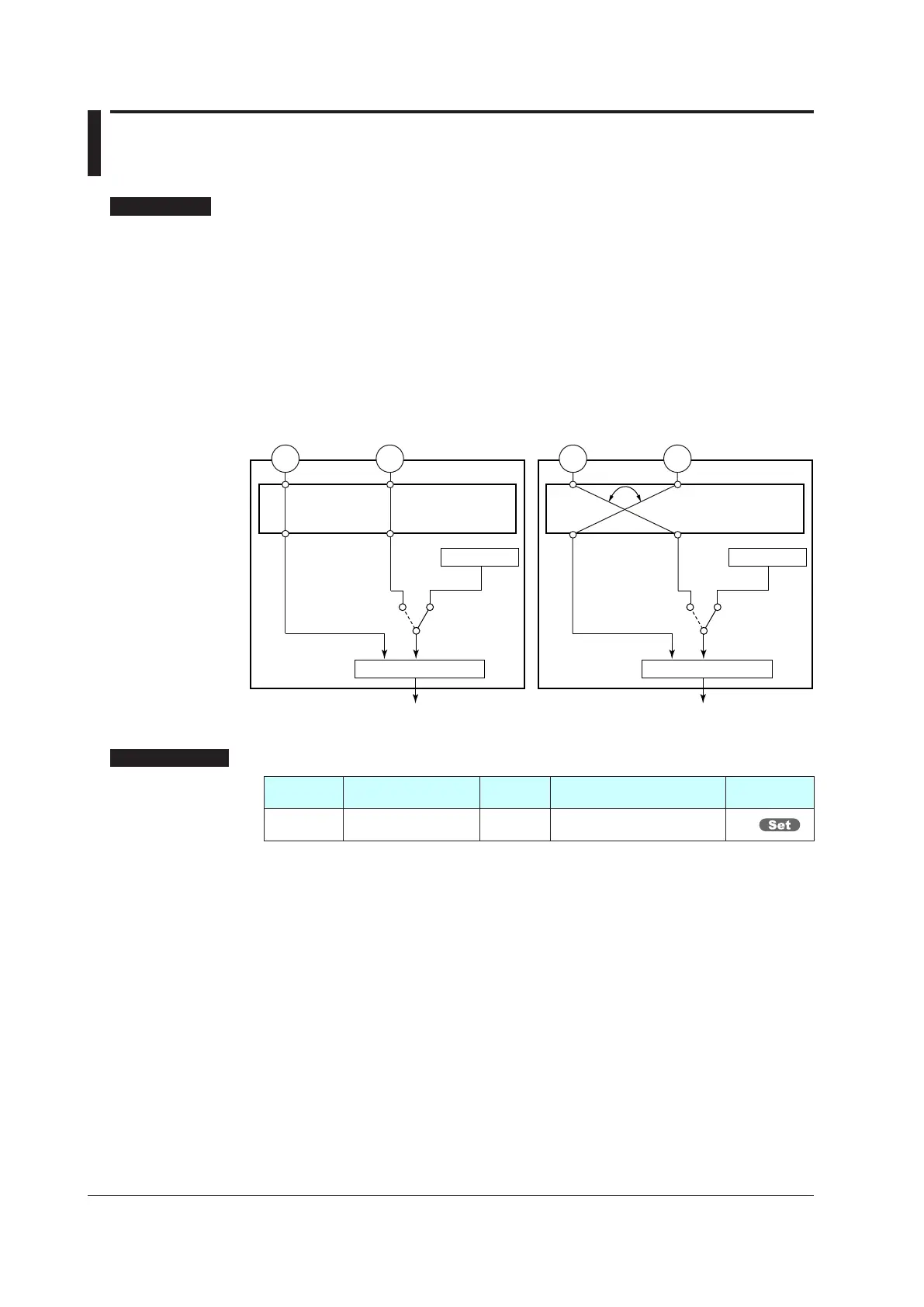
Normally,PV
terminalinputisusedasPV.
WhenRSPterminalisusedasPV,usetheladderprogramofLL50AParameterSetting
Software(soldseparately)toswitchthefunctionsofthePVterminalandRSPterminal.
► LL50AParameterSettingSoftware:LL50AParameterSettingSoftwareUser’sManual
PV inputPV input
RSP inputRSP input
LOCAL
REMOTE
LOCAL
REMOTE
Terminal Terminal Terminal Terminal
OUT
PID
PV RSP
Input ladder program Input ladder program
OUT
PID
PV RSP
Local SPLocal SP
When PV terminal is used as PV, and
RSP terminal is used as RSP.
When RSP terminal is used as PV,
and PV terminal is used as RSP.
Setting Details
Parameter
symbol
Name
Display
level
Setting range Menusymbol
RTD.S RTD wiring system STD
3-W: 3-wire system
4-W: 4-wire system
RSP

 Loading...
