17-5
IM 05P01C31-01EN
Installation and Wiring
17
17.4 Wiring
17.4.1 ImportantInformationonWiring
WARNING
1) Be sure to turn OFF the power supply to the controller before wiring to avoid an
electric shock. Use a tester or similar device to ensure that no power is being
supplied to a cable to be connected.
2)
Wiring work must be carried out by a person with basic electrical knowledge and
practical experience.
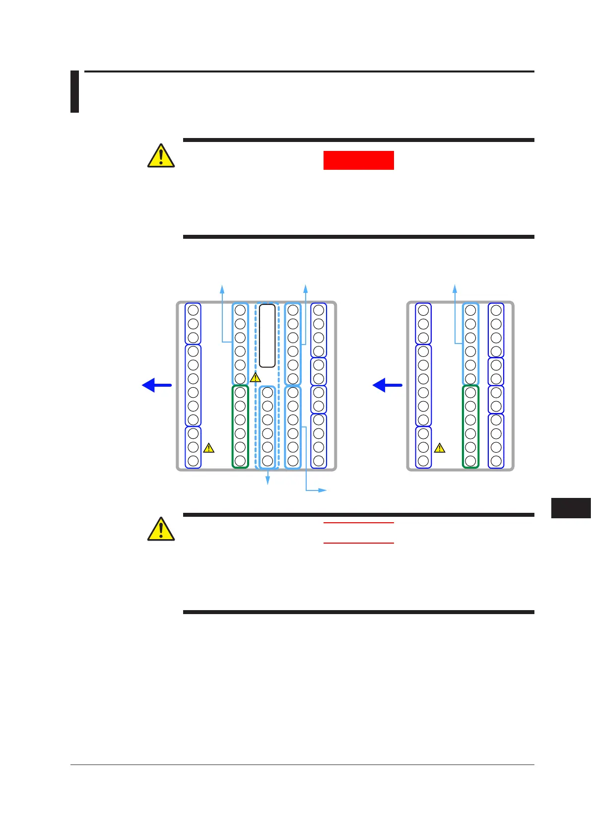
E4-terminal area E1-terminal area E1-terminal area
E3-terminal area E2-terminal area
UT55A Terminal Block Diagram UT52A Terminal Block Diagram
101
102
103
104
105
106
107
108
109
110
111
112
501
502
503
504
505
506
507
508
509
510
511
512
407
401
408
409
410
411
412
301
302
303
304
305
306
307
308
309
310
311
312
201
202
203
204
205
206
207
208
209
210
211
212
101
-112
501
-512
401
-412
301
-312
201
-212
111
301
302
303
304
305
306
307
308
309
310
311
312
201
202
203
204
205
206
207
208
209
210
101
102
103
104
105
106
107
108
109
110
211
212
101
-112
301
-312
201
-212
112
Wiring direction Wiring direction
CAUTION
● Whenconnectingtwoormorecrimp-onterminallugstothesingleterminal
block, bend the crimp-on terminal lugs before tightening the screw.
● Notethat
thewiringoftwoormorecrimp-onterminallugstothesinglehigh-
voltage terminal of the power supply and relay, etc. does not comply with the
safety standard.

 Loading...
