6-18
IM 05P01C31-01EN
(Continued)
OperationDisplay Display and operation description
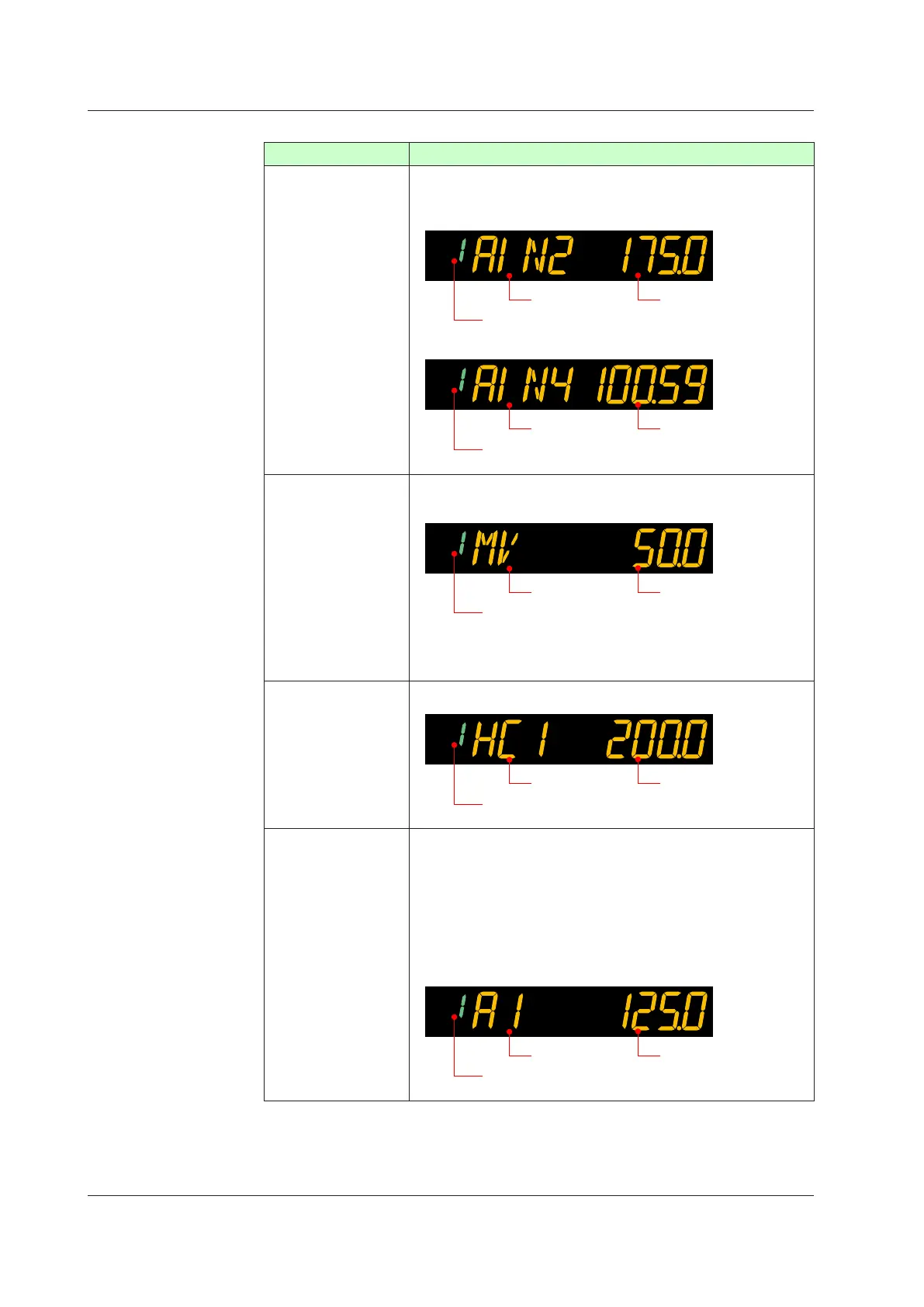
Analog Input
Display
PVdisplay:Displaysmeasuredinputvalue(PV).
Setpointdisplay:DisplaysPV,RSP,AIN2,orAIN4analoginputvalue.
AIN2 auxiliary analog input value
AIN2 input
Target setpoint (SP) number
Symbol
AIN4 auxiliary analog input value
AIN4 input
Target setpoint (SP) number
Symbol
Position
Proportional
Computation
OutputDisplay
PVdisplay:Displaysmeasuredinputvalue(PV).
Setpoint display: Displays position proportional computation output value
(internal computed value).
Internal
computed value
Target setpoint (SP) number
Symbol
Can be changed in MAN mode. The valve opens or closes so that the
valve’s feedback input value reaches the setpoint.
HeaterBreakAlarm
Current Display
PVdisplay:Displaysmeasuredinputvalue(PV).
Setpoint display: Displays measured heater current.
Heater break current
measured value
Target setpoint (SP) number
Symbol
SELECT Display
SELECT Display is for registering frequently-used parameters from
Parameter Setting Display, and for displaying them on Operation
Display so that the parameter settings can be easily changed in normal
operation.
PVdisplay:Displaysmeasuredinputvalue(PV).
Setpoint display: Displays and changes the registered parameter.
The following is the display example when the parameter A1 (alarm-1
setpoint) is registered.
Alarm setpoint
Target setpoint (SP) number
Symbol
6.1MonitoringandControlofOperationDisplays

 Loading...
