8-39
IM 05P01C31-01EN
Control Functions
8.1.6 LoopControlwithPVSwitching,Heating/coolingLoopControlwithPV
Switching,andPositionProportionalLoopControlwithPVSwitching
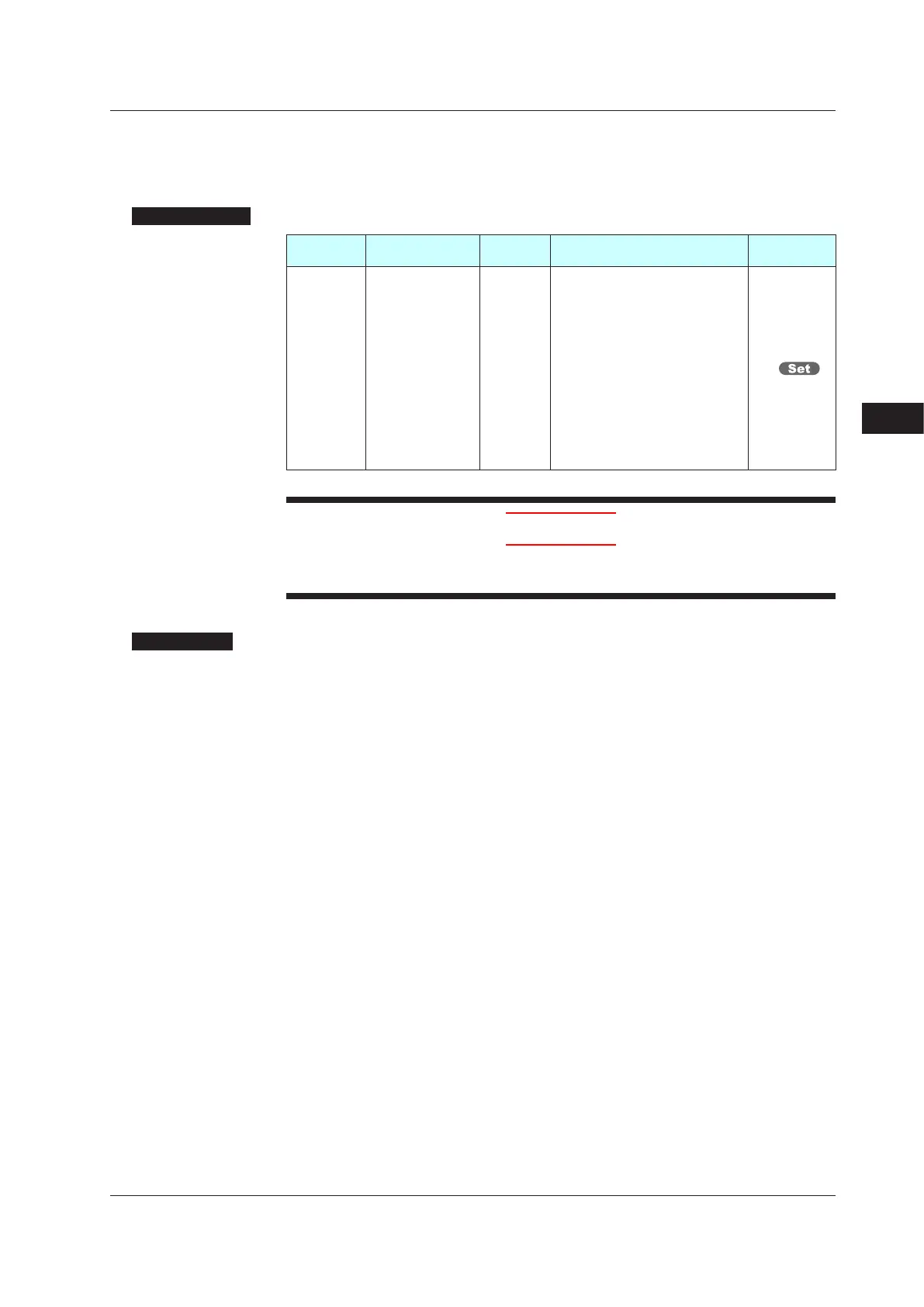
Setting Details
Parameter
symbol
Name
Display
level
Setting range Menusymbol
CTLM Control mode STD
SGL: Single-loop control
CAS1: Cascade primary-loop
control
CAS2: Cascade secondary-loop
control
CAS: Cascade control
BUM: Loop control for backup
PVSW:LoopcontrolwithPV
switching
PVSEL:LoopcontrolwithPV
auto-selector
PVHD:Loopcontrol
withPV-hold
function
CTL
CAUTION
• Someparameterswillbeinitializedifthecontrolmode(CTLM)ischanged.
• When using the ladder program, the control mode cannot be changed.
Description
ThesecontrolmodesusetwoPVinputs,whichareswitchedaccordingtoinputcontact
signals or measurement ranges.
Loop
controlwith
PVswitchingcanbeusedforStandardtypeorHeating/coolingtype
controller.
Heating/coolingloopcontrolwithPVswitchingcanbeusedforHeating/coolingtype
controller.
Positionproportionalloop
controlwithPVswitchingcanbeusedforPositionproportional
type controller.
► PIDcontrolandHeating/coolingcontrol:8.2SettingControlType(CNT)
DescriptionaboutLoopcontrolwithPVswitching
► PVrange:7.6AdjustingPVRangeforLoopControlwithPVSwitching
► Switchingaction:7.7SettingPVSwitchingMethodsofLoopControlwithPVSwitching
Uptofour10-segmentlinearizerapproximation/10-segmentlinearizerbiasescanbe
used for the input unit or output unit.
The Function block diagram describes only the basic functions.
Parameter symbols in the Function block diagram describe representative parameters.
For the functions and parameters which are not described in Function block diagram, see
the following.
► Contactinputassignment:12.1SettingContactInputFunction
► Contactoutputassignment:12.2SettingContactOutputFunction
► Contactoutputassignmenttoretransmissionoutputterminal:10.1SettingControlOutputType
► Analogoutputrangechange:10.14ChangingCurrentOutputRange
8
8.1SettingControlMode(CTLM)

 Loading...
