1-14
IM 05P01C31-01EN
1.7 DefinitionofMainSymbolsandTerms
MainSymbol
PV:Measuredinputvalue
SP: Target setpoint
OUT: Control output value
RSP: Remote setpoint
A/M: AUTO/MAN
C/A/M: CAS/AUTO/MAN
AUTO: Automatic
MAN: Manual
CASCADE, CAS: Cascade
REMOTE, REM: Remote
LOCAL, LCL: Local
E1, E2, E3, and E4: Terminal areas
► 17.4Wiring
Engineering Units
Inputrange(scale):thePVrangelowlimitissetto0%,andthehighlimitissetto100%
for conversion.
Inputrange(scale)
span:thePVrangespanissetto100%forconversion.
In this manual, the parameter setting range is described as the “input range” and “input
range span.” This means that engineering units are required to be set. Set a temperature
for temperature input.
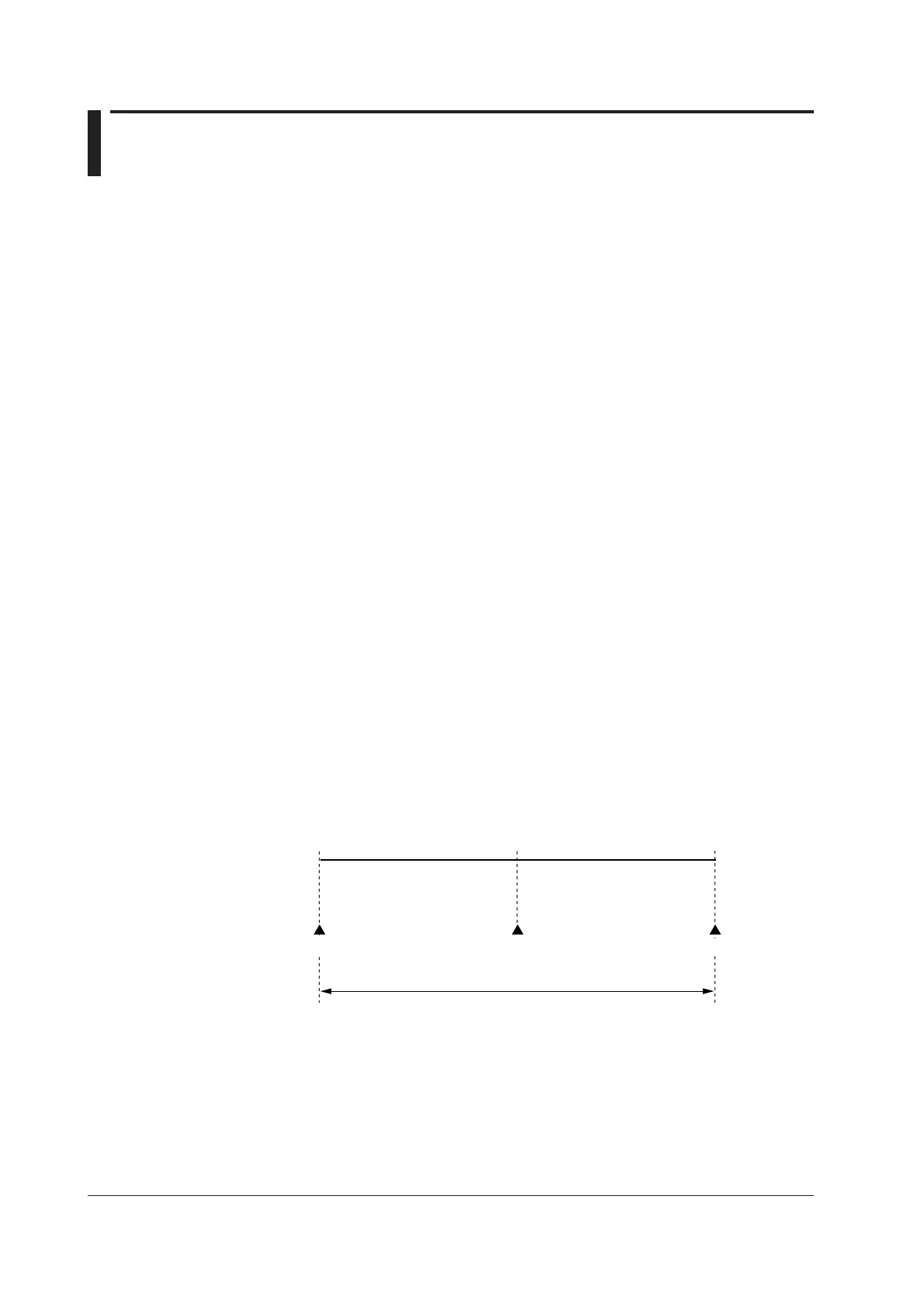
The following describes a conversion example.
WhenthePV
inputrangeis100to600°C,0%ofthePVrangeisequivalentto100°C,
50%ofthePVrangeisequivalentto350°C,and100%ofthePVrangeisequivalentto
600°C.
100%ofthePVrangespanisequivalentto500°C.
20%ofthePVrangespanisequivalentto100°C.
Minimum value of PV input range Maximum value of PV input range
100°C 600°C350°C
50% of PV input range
100% of PV input range span = 500°C
0% of PV input range 100% of PV input range
The above applies to the scale for voltage and current input.

 Loading...
