11-1
IM 05P01C31-01EN
AlarmFunctions
11
11.1 SettingAlarmType
Description
Thealarm-relatedparametersconsistoft
healarmtype(type,stand-byaction,energized/
de-energized,andlatchfunction),PVvelocityalarmtimesetpoint,alarmhysteresis,
alarm (On-/Off-) delay timer, and alarm setpoint.
In Cascade control, both of Loop 1 and Loop 2 have these parameters.
Alarm-relatedparameter Numberofsettings
Alarm type 8 (number of settings) x 2 (number of loops)
PVvelocityalarmtimesetpoint 8 (number of settings) x 2 (number of loops)
Alarm hysteresis 8 (number of settings) x 2 (number of loops)
Alarm (on-/off-) delay timer 8 (number of settings) x 2 (number of loops)
Alarm setpoint
8 (number of settings) x 8 (number of groups) x 2 (number of loops)
► Alarmhysteresis:11.3SettingHysteresistoAlarmOperation
► Alarmdelaytimer:11.4DelayingAlarmOutput(AlarmDelayTimer)
► Alarmsetpoint:6.5SettingAlarmSetpoint
Both of Loop-1 and Loop-2 have eight groups of alarms. The alarms are assigned to the
terminals for each control mode (parameter CTLM).
Factory default: Only four groups of alarm-related parameters are displayed.
► Terminalfunction:17.4.7ContactOutputWiring
Alarm output can be assigned to the unused control relay output or contact output.
► Controlrelayoutput:11.5SettingAlarmOutputtoControlRelayTerminal
► Contactoutput:12.2.1SettingFunctionofContactOutput
Energized/de-energizedofalarmoutputcanbechanged.
► Energized/de-energized:12.2.2ChangingContactTypeofContactOutput
To read the conditions of alarms, outputs, or latches via communication, see
Communication Interface User's Manual.
……
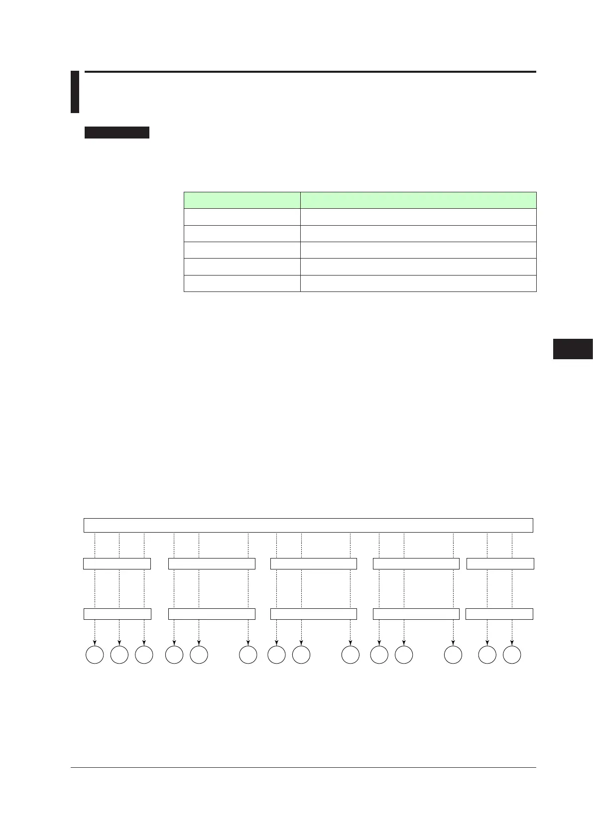
AL3AL2AL1
Alarm 1
(PV high limit)
* See “Appendix 1 Input and Output Table of Standard Model and Suffix Codes” for presence/absence of the terminals
DO11 to DO15, DO21 to DO25, and DO31 to DO35.
* OUT1 and OUT2 can be used for alarm output when the relay outputs are not used for control otuput.
* The above figure shows the case of single-loop control mode.
DO12DO11 DO15
……
DO22DO21 DO25
……
DO32DO31 DO35
Alarm conditions
Alarm conditions
Alarm conditions
Alarm conditions
Energized/de-energized
Energized/de-energized Energized/de-energized Energized/de-energized
…… ……
……
Alarm 2
(PV low limit)
Alarm 3
(PV high limit)
OUT2OUT1
Alarm conditions
Energized/de-energized
Alarm 4
(PV low limit)
No function
No function
No function Alarm 5 Alarm 8 No function
No function
No function
Alarm Function
Chapter11AlarmFunctions

 Loading...
