6-30
IM 05P01C31-01EN
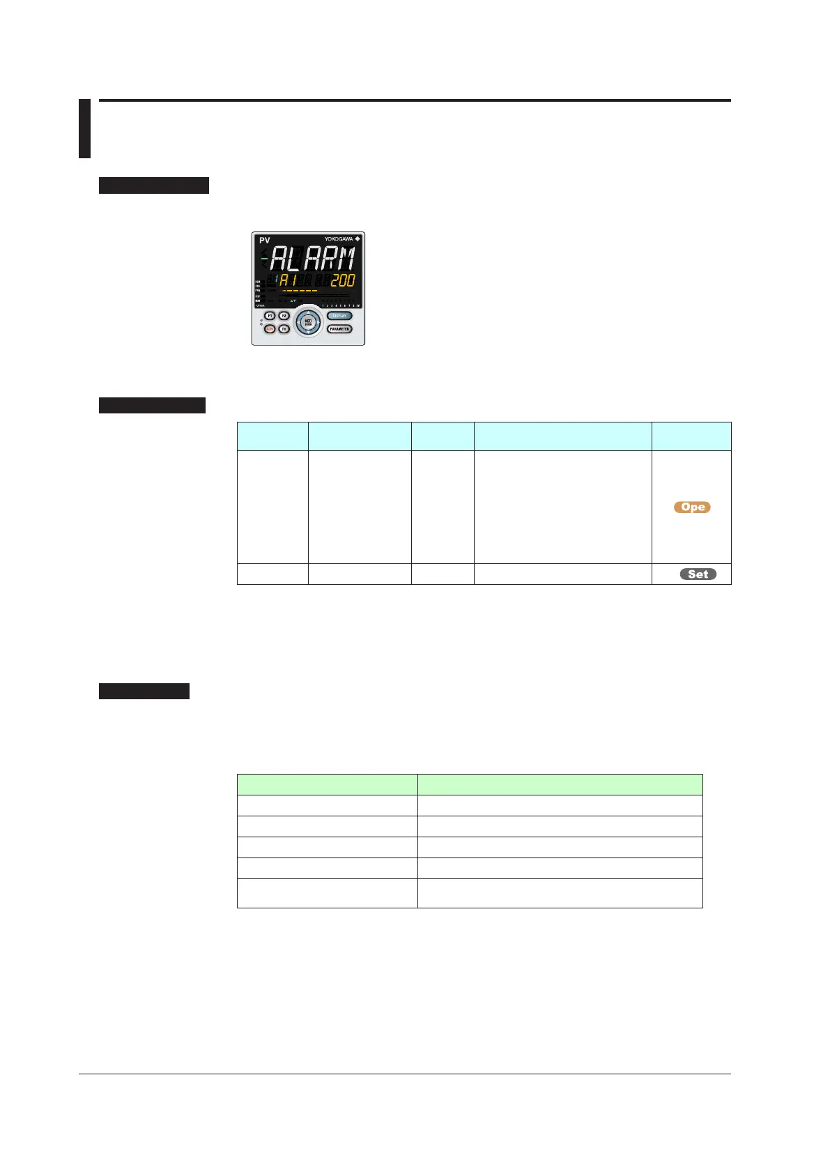
6.5 SettingAlarmSetpoint
Setting Display
Parameter Setting Display
Operation Display > PARAMETER or PARA key for 3
seconds (to [MODE] Menu Display) > Rightarrow key (to
[SP] Menu Display) >
SET/ENTER key (The setting parameter
is displayed.) > Down arrow key (The setting parameter is
displayed.)
In the setting Display for the alarm parameters, Displays can
be arbitrarily switched using the Up, Down, Left or Right arrow
key. Pressing the Left or Right arrow key changes the group.
(The group number is displayed on Group display.)
Setting Details
Parameter
symbol
Name
Display
level
Setting range Menusymbol
A1 to A8
Alarm-1 to -8
setpoint
EASY
Set a display value of setpoint of
PValarm,SP
alarm,deviation
alarm, output alarm, or velocity
alarm.
-19999 to 30000 (Set a value
within the input range.)
Decimal point position depends on
the input type
SP
ALNO. Number of alarms PRO 1 to 8 CTL
Note:1 When the alarm setpoint parameter is displayed, the group number is shown on Group
display.
Note2: The initial value of the parameter ALNO. is “4.” Four alarm setpoint parameters are displayed
for each SP group.
Note3: In Cascade control, the LP2 lamp is lit while the Loop-2 parameter is displayed.
Description
Each alarm type has eight alarm setpoints.
In Cascade control, each alarm type has eight setpoints for Loop 1 and Loop 2,
respectively.
Specifying the SP number (SPNO) determines the alarm setpoint to be used.
Alarm-relatedparameter Numberofsettings
Alarm type 8 (number of settings) x 2 (number of loops)
PVvelocityalarmtimesetpoint 8 (number of settings) x 2 (number of loops)
Alarm hysteresis 8 (number of settings) x 2 (number of loops)
Alarm delay timer 8 (number of settings) x 2 (number of loops)
Alarm setpoint
8 (number of settings) x 2 (number of loops) x 8 (number
of groups)
► Alarmtype:Chapter11Alarm
Functions

 Loading...
