ix
IM 05P01C31-01EN
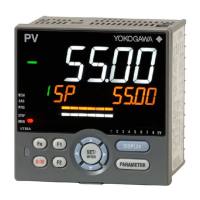
ModelandSuffixCodesofUT52A(forDetailedmodel)
[Style:S4]
Model Suffix code
Optional
suffix
code
Description
UT52A
Digital Indicating Controller (provided with 3 DIs, and 3 DOs) (Power supply:
100-240VAC)
Fixed code -NNN Always "-NNN”
Di
splay language (*1)
-1 English
-2 German
-3 French
-4 Spanish
Case color
0 White (Lithg gray)
1 Black (Light charcoal gray)
Output 1 (*2) (*3) (*4)
-A Analog output (current/voltage pulse)
-R Relay output (c-contact)
-U Universal output (current/voltage pulse/relay)
-T Triac output
-P Position proportional output
Output 2 (*2) (*3) (*4) (*5)
A Analog output (current/voltage pulse)
R Relay output (a-contact)
U Universal output (current/voltage pulse/relay)
N None
Retransmission output /RT Retransmissionoutputor15VDCpowersupply
Heater break alarm (*3) /HA Heater break alarm
E1 terminal area (*5) (*6)
/R1 Remote (1 additional aux. analog) input and 1 additional DI
/U1 1additionaluniversalinput(TC/RTD/DCV/mA)
/L1 24VDClooppowersupply
/CH1 RS485 communication (Max. 38.4 kbps, 2-wire/4-wire)
/RCH1
Remote (1 additional aux. analog) input, 1 additional DI, and RS485
communication (Max.38.4 kbps, 2-wire)
/LCH1 24VD
Clooppow
ersupplyandRS485communication(Max.38.4kbps,2-wire)
/X1 5 additional DIs
/Y1 5 additional DOs
/W1 2 additional DIs and 2 additional DOs
Power supply /DC Powersupply24VAC/DC
Additional treatment (*7) /CT Coating
*1:
English, German, French, and Spanish can be displayed as the guide display.
*2: For heating/cooling output, both Output 1 and Output 2 should be s
pecified. Not available when Output 2 is “N.” For
position proportional output, specify “-P” for Output 1 and “N” for Output 2.
*3: The /HA option can be specified only when the code for Output 1 and 2 is “-AN”, “-RN”, “-UN” or “-TN.”
*4: When the code for Output 1 is "-R" or "-U" and Output 2 is "R" or "U", Output 1 is changed from the contact point c to
the contact point a. When the code for Output 1 is specified to "-T", only "A" or "N" is available for Output 2.
*5:
The /L1 or /LCH option can be specified only when the code for Output 2 is “N.”
*6: Only one option is available for E1 terminal area.
*7: When the /CT option is specified, the UT52A does not conform to the safety standards (UL and CSA) and CE marking.
CoatingTreatment
(1) HumiSeal coating treatment
Apply HumiSeal coating to the printed circuit board assembly.
Do not apply HumiSeal coating to the following parts: connector, gold-plated contact
area, relay part, RJC device, and in the vicinity of the push switch/LED lamp.
(2) Apply terminal coating to the gold-plated contact area on the printed circuit board.
Notes
▪Thereare
twotreatmentsasdescribedabove,butwedonotguaranteetheir
effectiveness.
We do not supply any test data on these treatments.
▪
Donotapplyanytreatmenttothescrewterminalareaonthebacksideofthe
instrument.

 Loading...