17-8
IM 05P01C31-01EN
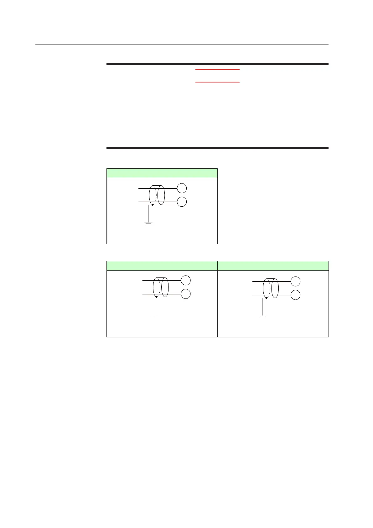
17.4.3 Remote(AuxiliaryAnalog)InputWiring
CAUTION
1) Be careful of polarity when wiring inputs. Reversed polarity can damage the UT.
2) Keep the remote (auxiliary analog) input signal line as far away as possible from
the power supply circuit and ground circuit.
3) For TC input (remote input with direct input), use shielded compensating lead
wires for wiring. For RTD input, use shielded wires that have low conductor
resistance and cause no significant dif
ferences in resistance between the three
wires.
4) If there is a risk of external lightning surges, use a lightning arrester etc.
UT55A/UT52A
Remoteinput(E1-terminalarea)
306
305
–
+
+
–
DC voltage
Class D grounding
(grounding resistance of 100 Ω or less)
Shield
RSP
UT55A
Auxiliaryanaloginput(E2-terminalarea) Auxiliaryanaloginput(E4-terminalarea)
312
311
–
+
+
–
DC voltage
Class D grounding
(grounding resistance of 100 Ω or less)
Shield
AIN2
506
505
–
+
+
–
DC voltage
Class D grounding
(grounding resistance of 100 Ω or less)
Shield
AIN4
Use
RSPRemoteInput(E1-terminalarea)
InSingle-loopcontrolorLoopcontrolwithPV-holdfunction,usedforremoteinput.
In Cascade primary-loop control, remote input is used for output tracking input.
In Cascade secondary-loop control, remote input is used for cascade input.
In Cascade control, remote input is usedforLoop-2
PVinput.
In Loop control for backup, remote input is used for output tracking input.
InLoopcontrol
withPVswitchingorLoopcontrolwithPVauto-selector,remote input is
usedforPV
input2.
AIN2AuxiliaryAnalogInput(E2-terminalarea)
InLoopcontrolwithPVauto-selectorfor3inputsor4inputs,auxiliaryanaloginput(E-2
terminalarea)isusedforPVinput3.
17.4 Wiring

 Loading...
