17-7
IM 05P01C31-01EN
Installation and Wiring
17
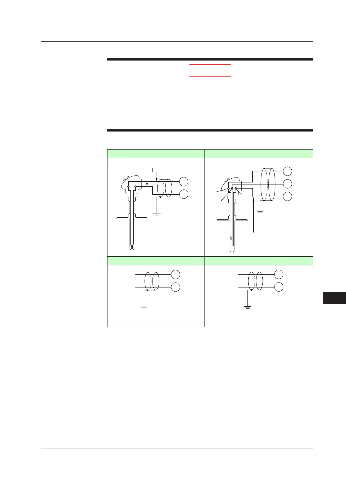
17.4.2 PVInputWiring
CAUTION
1) Be careful of polarity when wiring inputs. Reversed polarity can damage the UT.
2)KeepthePVinputsignallineasfarawayaspossiblefromthepowersupply
circuit and ground circuit.
3) For TC input, use shielded compensating lead wires for wiring. For RTD input,
use shielded wires that have low conductor resistance and cause no significant
dif
ferences in resistance between the three wires.
4) If there is a risk of external lightning surges, use a lightning arrester etc.
UT55A/UT52A
TC Input RTDInput(3-wiresystem)
203
202
TC
–
+
Compensating lead wire
Class D grounding
(grounding resistance
of 100 Ω or less)
Shield
PV
203
202
201
RTD
A
B
b
Lead wire resistance per wire of
10 Ω or less. Make the resistance
of the three wires equal.
A
b
B
Class D grounding
(grounding resistance
of 100 Ω or less)
Shield
PV
DCVoltage(mV,V)Input DCCurrent(mA)Input
203
202
–
+
+
–
DC voltage
Class D grounding
(grounding resistance of 100 Ω or less)
Shield
PV
204
203
–
+
+
–
DC current
Class D grounding
(grounding resistance of 100 Ω or less)
Shield
PV
Use
In Single-loop control, Cascade primary-loop control, Cascade secondary-loop control,
Loopcontrolfor
backup,orLoopcontrolwithPV-holdfunction,PVinputisusedforPV
input.
InLoopcontrol
withPVswitchingorLoopcontrolwithPVauto-selector,PVinputisused
forPVinput1.Remoteinput(E1-terminalarea)isusedforPVinput2.InLoopcontrol
withPVauto-selectorfor3inputsor4inputs,auxiliaryanaloginputsareusedforPV
input3andPVinput4.
InCascadecontrol,PVinputisusedforLoop-1PVinput.Remoteinput(E1-terminal
area)isusedforLoop-2PVinput.
17.4 Wiring

 Loading...
