7-7
IM 05P01C31-01EN
Input(PV,Remote,andAuxiliaryAnalog)Functions
7.1.4 CorrectingInputValue
(1)SettingBiasandFilter
Description
PVInputBias
ThePVinput
biasallowsbiastobesummedwithinputtodevelopameasuredvaluefor
display and control use inside the controller.
Thisfunctioncan
alsobeusedforfineadjustmenttocompensateforsmallinter-
instrument differences in measurement reading that can occur even if all are within the
specified instrument accuracies.
PVinputbiasisusedfornormaloperation.
PV input value + =PV input bias PV value inside the controller
Temperature sensed
by thermocouple
Compensation
value
Estimated material
temperature
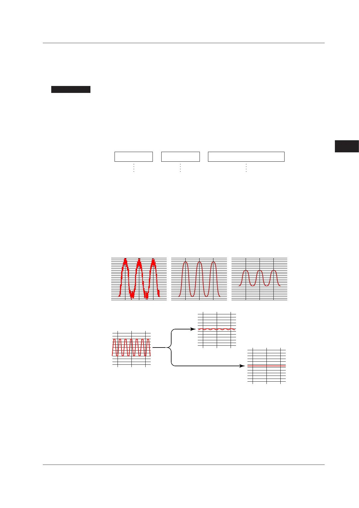
PVInputFilter
If input noise or variations cause the low-order display digits to fluctuate so that the
displayed value is difficult to read, a digital filter can be inserted to smooth operation.
This filter provides a first-order lag calculation, which can remove more noise the larger
the time constant becomes. However, an excessively large time constant will distort the
waveform.
PV
inputfilter
isusedfornormaloperation.
Actual input
With a small time constant With a large time constant
Input
Filtering for 2 sec
Filtering for 10 sec
Analog Input Bias
Analog input bias is used to correct sensor-input characteristics, compensating lead wire
errors, and so on.
Analog Input Filter
The analog input filter is used to remove noise from an input signal. This filter provides
a first-order lag calculation, which can remove more noise the larger the time constant
becomes. However, an excessively large time constant will distort the waveform.
7
7.1SettingFunctionsofPVInput,RemoteInput,andAuxiliaryAnalogInput

 Loading...
