プログラムパターン番号表示画面(表示のみ)
パラメータRMS=PROG
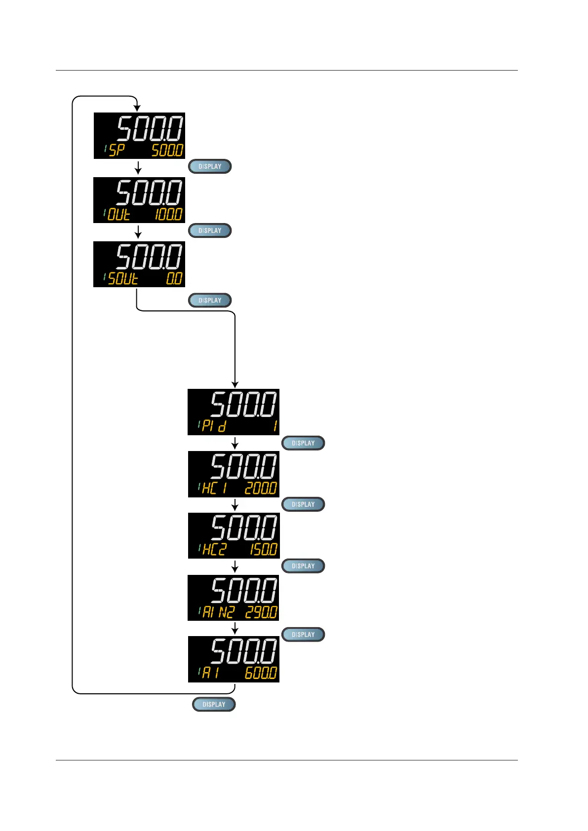
SP Display (SP can be changed.)
OUT Display (Main setting-side OUT can be changed in MAN mode.)
OUT Display (Sub-setting-side OUT can be changed in MAN mode.)
PID Number Display (display only)
(Factory default: non-display)
Heater Break Alarm-1 Current Display (display only)
(Only for Heater break alarm option)
Heater Break Alarm-2 Current Display (display only)
(Only for Heater break alarm option)
SELECT Displays 1 to 5
(Displayed only when SELECT Display is registered.)
(The figure on the left is the example of the parameter A1 (alarm-1
setpoint)).
Analog Input Displays (display only)
(Factory default: non-display)
PV: PV analog input,
RSP: RSP analog input (E1-terminal area),
AIN2: AIN2 analog input (E2-terminal area),
AIN4: AIN4 analog input (E4-terminal area)
(Only for each aux. analog input)

 Loading...
