6-1
IM 05P01C31-01EN
MonitoringandControlofRegularOperations
6
6.1 MonitoringandControlofOperationDisplays
6.1.1 OperationDisplayTransitionsinSingle-loopControl,CascadePrimary-
loopControl,CascadeSecondary-loopControl,LoopControlforBackup,
andLoopControlwithPV-holdFunction.
(The displays only for the Standard type are displayed in Cascade primary-loop control.)
► Display/Non-display of Operation Display: 13.3.5
Setting Display/Non-display of Operation Display
► Registration of SELECT Display: 13.1.3 Registering SELECT Display (Up to 5 displays)
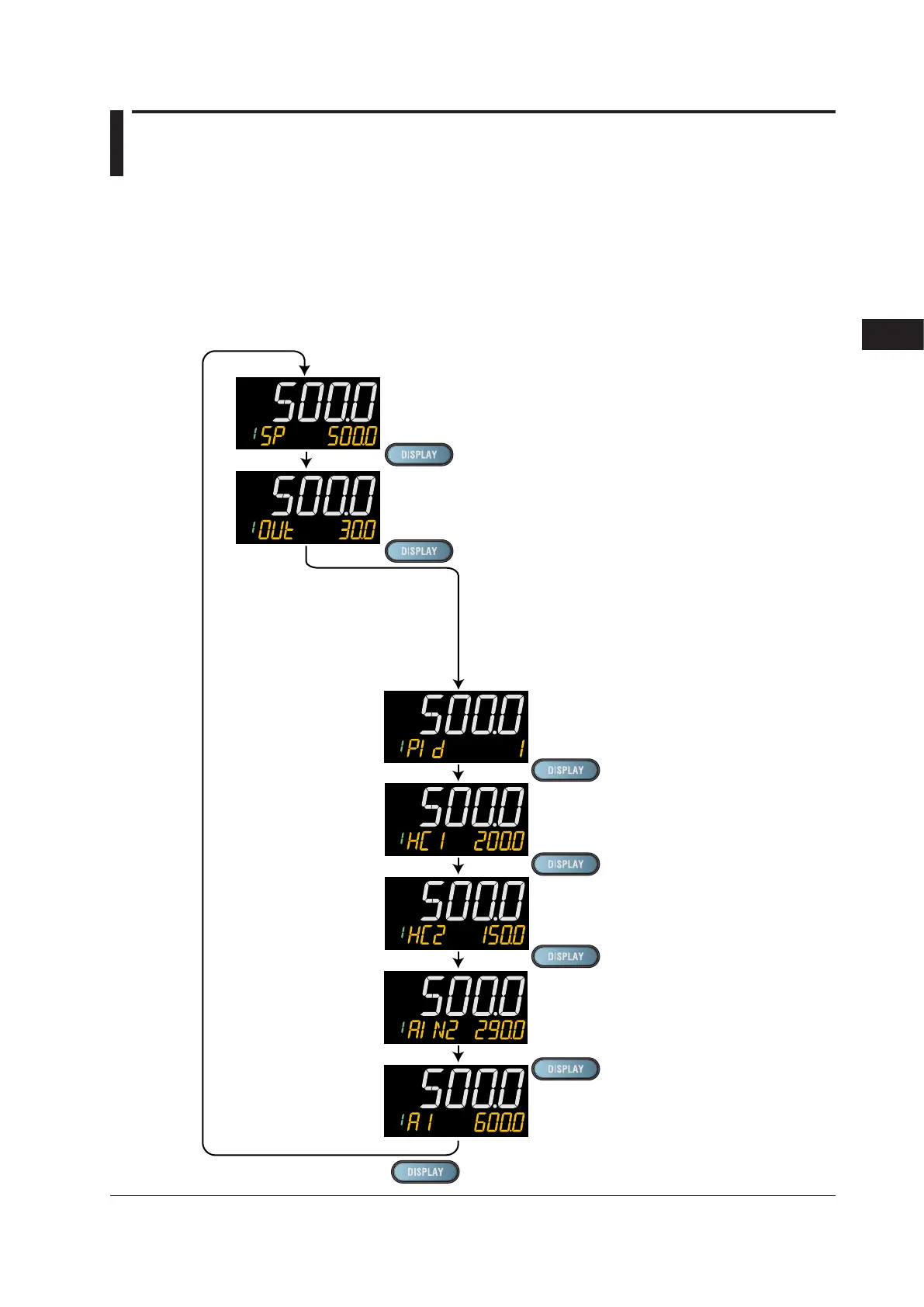
Standard Type
Program Pattern Number Display (Display only)
Parameter RMS = PROG
SP Display (SP can be changed.)
OUT Display (OUT can be changed in MAN mode.)
PID Number Display (display only)
(Factory default: non-display)
Heater Break Alarm-1 Current Display (display only)
(Only for Heater break alarm option)
Heater Break Alarm-2 Current Display (display only)
(Only for Heater break alarm option)
SELECT Displays 1 to 5
(Displayed only when SELECT Display is registered.
(The figure on the left is the example of
the parameter A1 (alarm-1 setpoint).)
Analog Input Displays (display only)
(Factory default: non-display)
PV: PV analog input,
RSP: RSP analog input (E1-terminal area),
AIN2: AIN2 analog input (E2-terminal area),
AIN4: AIN4 analog input (E4-terminal area)
(Only for each aux. analog input)
Chapter6MonitoringandControlofRegularOperations

 Loading...
