13-11
IM 05P01C31-01EN
Display, Key, and Security Functions
Setting Details
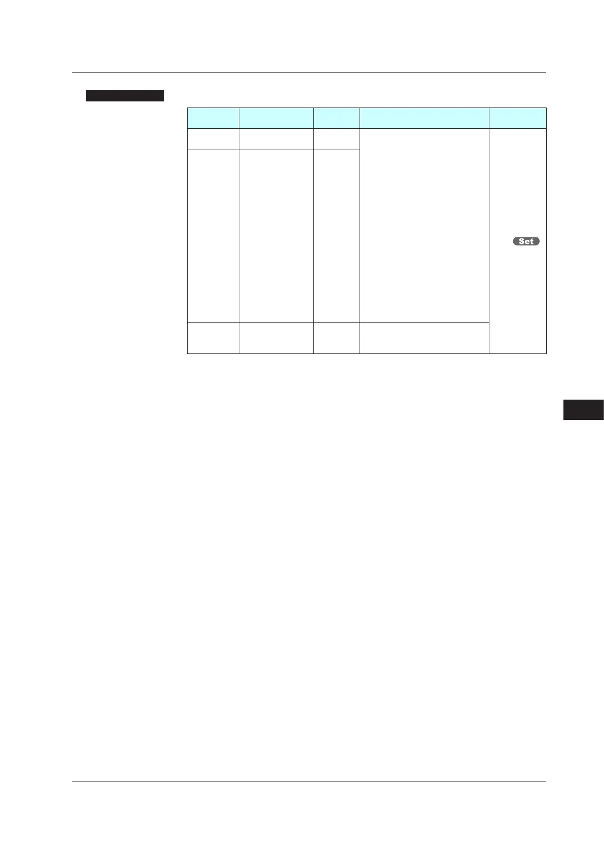
Parameter
symbol
Name
Display
level
Setting range Menusymbol
BAR1
Upper bar-graph
display registration
STD
0: Disable
1:OUT, Heating-side OUT, Internal
value in Position proportional
control
2: Cooling-side OUT
3:PV
4: SP
5: Deviation
6:
Loop-2 OUT, Loop-2 heating-side OUT
7: Loop-2 cooling-side OUT
8:Loop-2PV
9: Loop-2 SP
10: Loop-2 deviation
11 to 16: Disable
17:
Feedback input (valve opening)
18:PVterminalsanaloginput
19: RSP terminals analog input
20: AIN2 terminals analog input
21: AIN4 terminals analog input
DISP
BAR2
Lower bar-graph
display registration
STD
BDV
Bar-graph
deviation display
band
STD
0.0to100.0%
ofPVinputrange
span (EUS)
Note1:Thebar-graphdeviationdisplayband(BDV)isenabledwhenthedeviationissettothe
BAR1 or BAR2.
Note2: In Cascade control, the LP2 lamp is lit while the Loop-2 parameter is displayed.
13
13.1 Setting Display Functions

 Loading...
