(Continued)
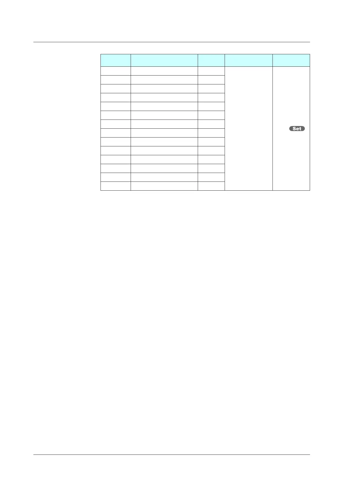
Parameter
symbol
Name
Display
level
Setting range Menusymbol
MODE [MODE] menu lock PRO
OFF: Display
ON: Nondisplay
MLOC
CS [CS] menu lock PRO
SP [SP] menu lock PRO
SPS [SPS] menu lock PRO
ALRM [ALRM] menu lock PRO
PVS [PVS]menulock PRO
PID [PID] menu lock PRO
TUNE [TUNE] menu lock PRO
ZONE [ZONE]menulock PRO
PPAR [PPAR] menu lock PRO
PYS1 [PYS1] menu lock PRO
PYS2 [PYS2] menu lock PRO
PYS3 [PYS3] menu lock PRO
PYS4 [PYS4] menu lock PRO
Note 1: When each parameter is displayed, the terminal area (E1 to E4) is displayed on Group
display according to the suffix code and optional suffix code.
Note 2: In Cascade control, the LP2 lamp is lit while the Loop-2 parameter is displayed.
13.3 Setting Security Functions

 Loading...
