16-13
IM 05P01C31-01EN
Troubleshooting,Maintenance,andInspections
16
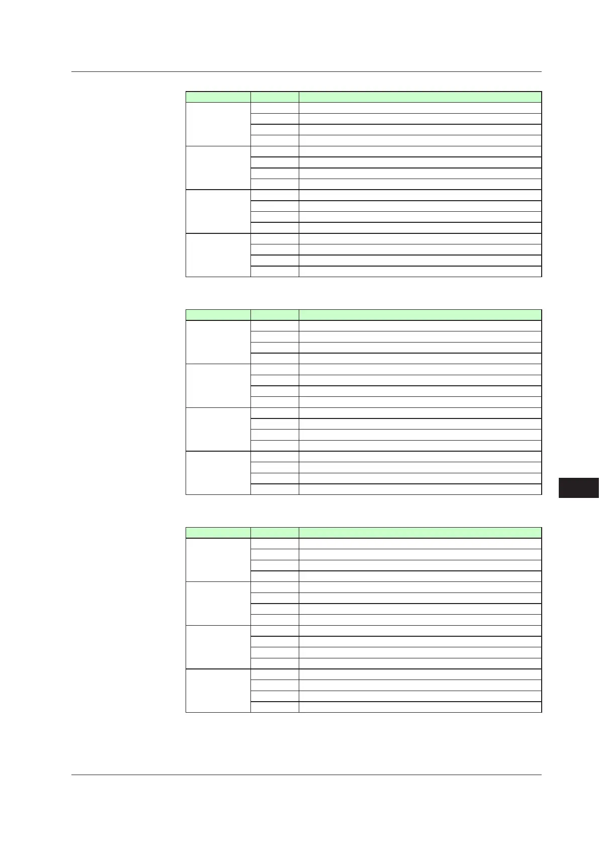
ParameterOP.ER
Displayed digit bit Description
1st digit 0 Non responding hardware in E1-terminal area
1 Non responding hardware in E2-terminal area
2 Non responding hardware in E3-terminal area
3 –
2nd digit 4 Non responding hardware in E4-terminal area
5 –
6 –
7 –
3rd digit 8 Communication error in E1-terminal area
9 –
10 Communication error in E3-terminal area
11 –
4th digit 12 Communication error in E4-terminal area
13 –
14 –
15 –
Parameter
AD1.E
Displayed digit bit Description
1st digit 0 ADCerrorof
PVinput
1 ADC error of RSP input (E1-terminal area)
2 ADC error of AIN2 input (E2-terminal area)
3 –
2nd digit 4 ADC error of AIN4 input (E4-terminal area)
5 RJC
errorof
PVinput
6 RJC error of RSP input
7 –
3rd digit 8 PV
inputburnout
error
9 RSP input (E1-terminal area) burnout error
10 AIN2 input (E2-terminal area) burnout error
11 –
4th digit 12 AIN4 input (E4-terminal area) burnout error
13 –
14 –
15 –
Parameter
AD2.E
Displayed digit bit Description
1st digit 0 Feedback input resistor/current burnout
1 Automatic
valveposition
adjustmenterror
2 –
3 –
2nd digit 4 –
5 –
6 –
7 –
3rd digit 8 –
9 –
10 –
11 –
4th digit 12 –
13 –
14 –
15 –
16.1Troubleshooting

 Loading...
