18-10
IM 05P01C31-01EN
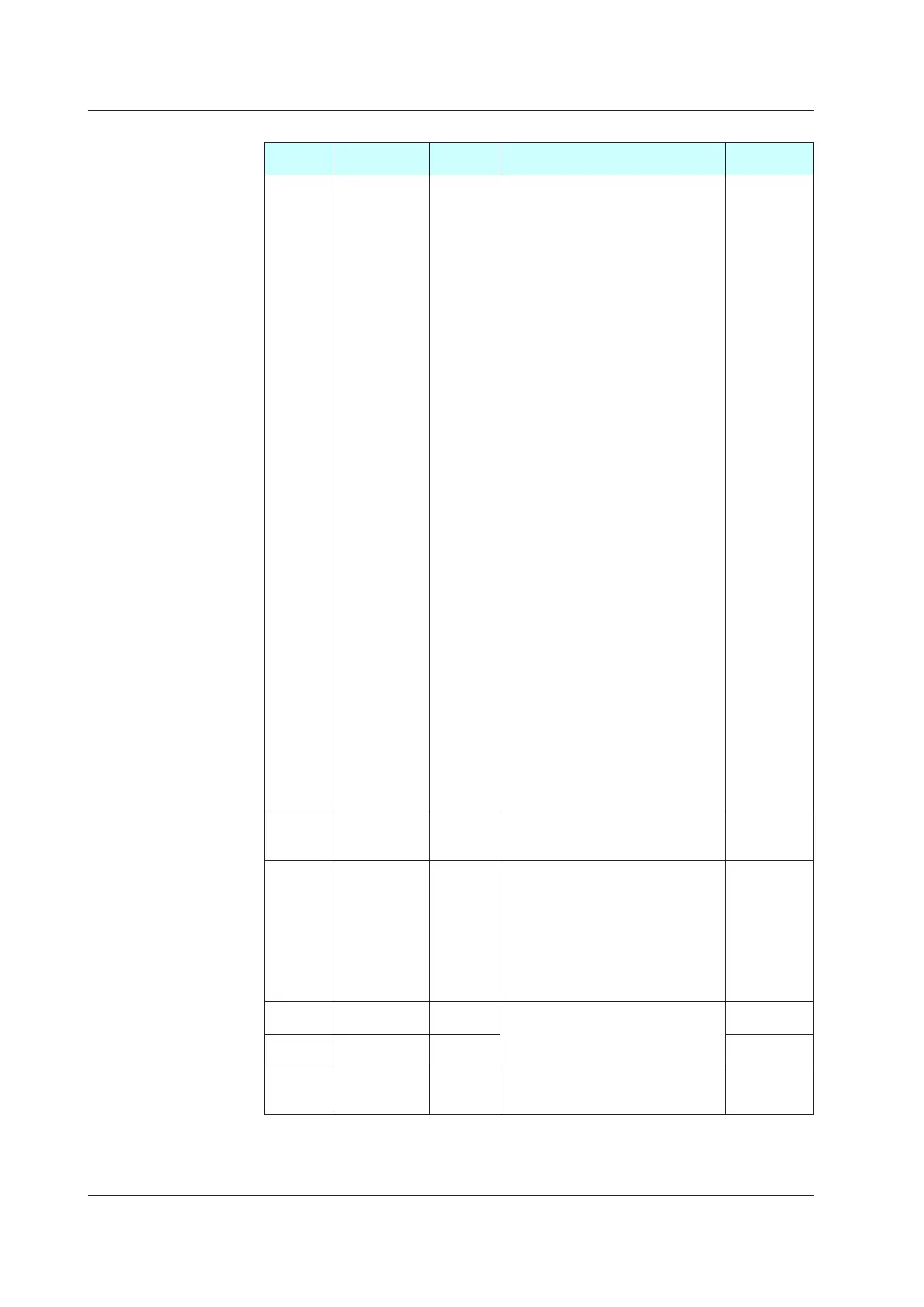
AlarmFunctionSettingMenu(Menu:ALRM)
Parameter
symbol
Name
Display
level
Setting range Initialvalue
AL1 to AL8
Alarm-1 to -8
type
EASY
Set a 5-digit value in the following order.
[Alarm type: 2 digits (see below)] +
[Without (0) or With (1) Stand-by action]
+[Energized(0)
orDe-energized(1)]+
[Latch action (0/1/2/3/4)]
For latch action, see chapter 11.
Alarm type: 2 digits
00: Disable
01:PVhighlimit
02:PVlowlimit
03: SP high limit
04: SP low limit
05: Deviation high limit
06: Deviation low limit
07: Deviation high and low limits
08: Deviation within high and low limits
09: Target SP high limit
10: Target SP low limit
11: Target SP deviation high limit
12: Target SP deviation low limit
13:
Target SP deviation high and low limits
14: Target SP deviation within high and
low limits
15: OUT high limit
16: OUT low limit
17: Cooling-side OUT high limit
18: Cooling-side OUT low limit
19:AnaloginputPVhighlimit
20:AnaloginputPVlowlimit
21: Analog input RSP high limit
22: Analog input RSP low limit
23: Analog input AIN2 high limit
24: Analog input AIN2 low limit
25: Analog input AIN4 high limit
26: Analog input AIN4 low limit
27: Feedback input high limit
28: Feedback input low limit
29:PVvelocity
30: Fault diagnosis
31: FAIL
AL1,AL3:PV
high limit (01)
Without Stand-
by action (0)
Energized(0)
Latch action
(0)
AL2,AL4:PV
low limit (02)
Without Stand-
by action (0)
Energized(0)
Latch action
(0)
VT1toVT8
PVvelocity
alarm time
setpoint 1 to 8
EASY 0.01 to 99.59 (minute.second) 1.00
HY1 to
HY8
Alarm-1 to -8
hysteresis
EASY
Set a display value of setpoint of
hysteresis.
-19999 to 30000 (Set a value within the
input range.)
Decimal point position depends on the
input type.
When the decimal point position for the
input type is set to "1", the initial value
of the hysteresis is "1.0".
10
DYN1 to
DYN8
Alarm-1 to -8
On-delay timer
STD
0.00 to 99.59 (minute.second)
0.00
DYF1 to
DYF8
Alarm-1 to -8
Off-delay timer
PRO 0.00
AMD Alarm mode STD
0: Always active
1: Not active in STOP mode
2: Not active in STOP or MAN mode
0
In Cascade control, the following parameters are also displayed for secondary loop. (the LP2 lamp
is lit)
•Parameter:AL1
toAL8,VT1toVT8HY1toHY8,DYN1toDYN8,DYF1toDYF8,AMD
18.2ListofParameters

 Loading...
