18-38
IM 05P01C31-01EN
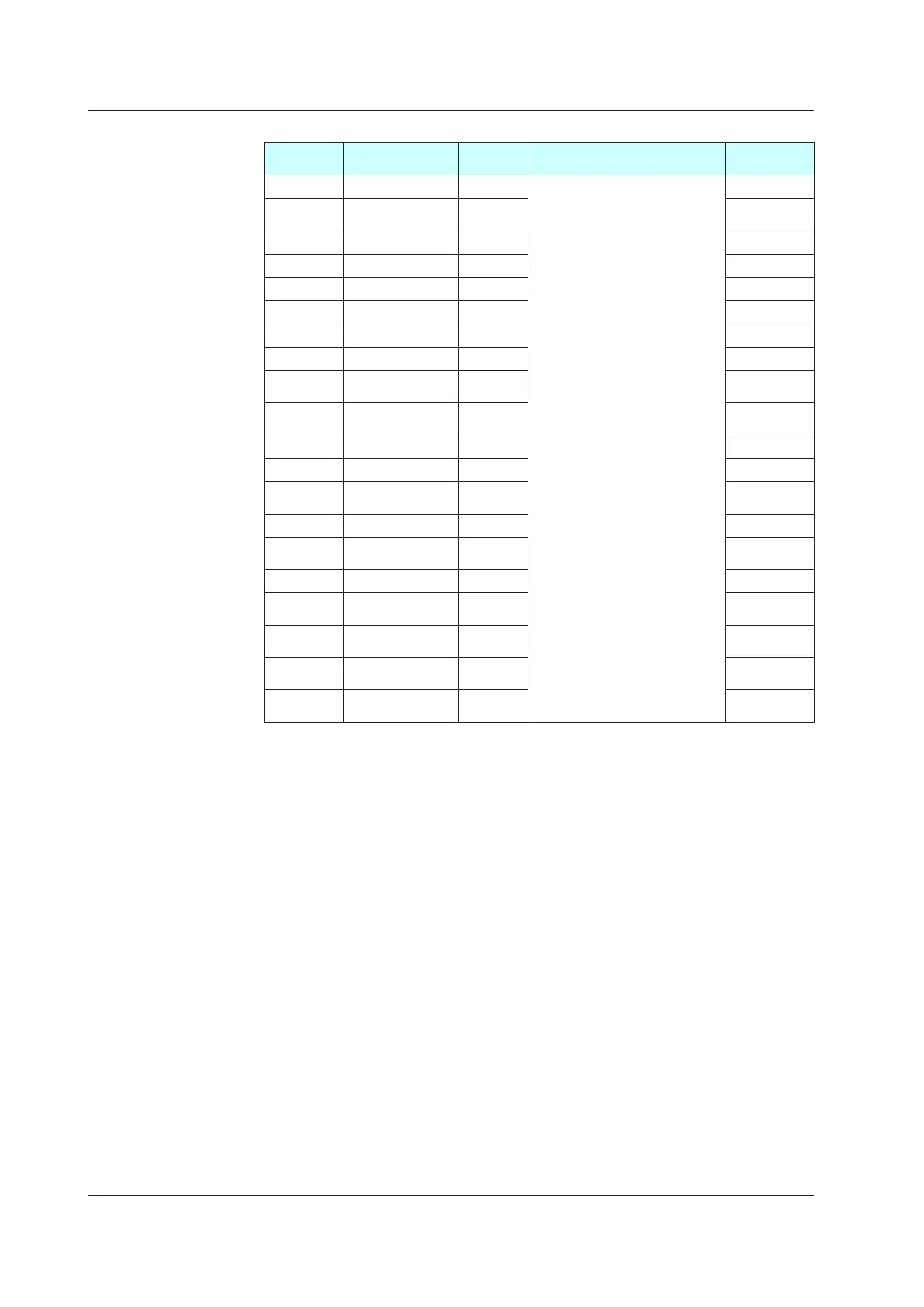
DIFunctionRegistrationMenu(Menu:DI.SL)
Parameter
symbol
Name
Display
level
Setting range Initialvalue
A/M AUTO/MAN switch STD
Set an I relay number of contact
input.
Set “OFF” to disable the function.
Standard terminals
DI1: 5025, DI2: 5026, DI3: 5027
E1-terminal area
DI11: 5041, DI12: 5042,
DI13: 5043, DI14: 5044,
DI15: 5045, DI16: 5046
E2 -terminal area
DI21: 5057, DI22: 5058,
DI23: 5059, DI24: 5060,
DI25: 5061, DI26: 5062
E3-terminal area
DI31: 5073, DI32: 5074,
DI33: 5075, DI34: 5076,
DI35: 5077
E4-terminal area
DI41: 5089, DI42: 5090,
DI43: 5091, DI44: 5092,
DI45: 5093, DI46: 5094
5025
R/L
REMOTE/LOCAL
switch
STD 5046
S/R STOP/RUN switch STD 5026
CAS Switch to CAS STD OFF
AUTO Switch to AUTO STD OFF
MAN Switch to MAN STD OFF
REM Switch to REMOTE STD OFF
LCL Switch to LOCAL STD OFF
AT
Auto-tuning START/
STOP switch
STD OFF
TRK
Output tracking
switch
PRO OFF
SW PVswitch PRO OFF
PVHD PVhold PRO OFF
CTOA
CAS to AUTO
switch
PRO OFF
LAT Latch release STD OFF
LCD
LCD backlight ON/
OFF switch
STD OFF
PVRW PVred/whiteswitch STD OFF
MG1
Message display
interruption 1
PRO OFF
MG2
Message display
interruption 2
PRO OFF
MG3
Message display
interruption 3
PRO OFF
MG4
Message display
interruption 4
PRO OFF
In Cascade control, the following parameters are also displayed for secondary loop. (the LP2 lamp
is lit)
•
Parameter:R/L,
REM,LCL,PVRW
18.2ListofParameters

 Loading...
