19-3
IM 05P01C31-01EN
Specifications
19
• Input sampling (control) period: Select from among 50, 100, and 200 ms
• Burnout detection:
Functions at TC, RTD, and standard signal
Upscale, downscale, and off can be specified.
Forstandardsignal,burnoutisdeterminedtohaveoccurredifitis0.1Vor0.4mA
or less.
• Input bias current: 0.05 µA (for TC or RTD)
•
Measurement current (RTD): About 0.16 mA
• Input resistance:
TCormVinput:1MΩormore
Vinput:About1MΩ
mAinput:About250Ω
• Allowable signal source resistance:
TCormVinput:250Ωorless
Effectsofsignalsourceresistance:0.1µV/Ωorless
DCvoltageinput:2kΩorless
Effectsofsignalsourceresistance:About0.01%/100Ω
• Allowable wiring resistance:
RTDinput:Max.150Ω/wire(Theconductorresistancebetweenthethreewires
shall be equal.)
Wiringresistance
effect:±0.1ºC/10Ω
• Allowable input voltage/current:
TC,mV,mAorRTDinput:±10VDC
Vinput:±20VDC
mA input: ±40 mA
• Noiserejectionratio:
Normalmode:40dBormore(50/60Hz)
Commonmode:120dBormore(50/60Hz)
For100-240VAC,thepowerfrequencycanbesetmanually.Automaticdetection
is also available.
For24
VAC/DC,thepowerfrequencycanbesetmanually.
• Referencejunctioncompensationerror:
±1.0ºC (15 to 35ºC)
±1.5ºC (-10 to 15ºC, 35 to 50ºC)
• Applicable standards: JIS/IEC/DIN (ITS-90) for
TC and RTD
Auxiliary Analog Input
• Use: Remote setpoint setting, external compensating input, auxiliary input for
computation, etc.
• Number of inputs: See the table of Model and Suffix Codes
• Input type, instrument range, and measurement accuracy: See the table below
.
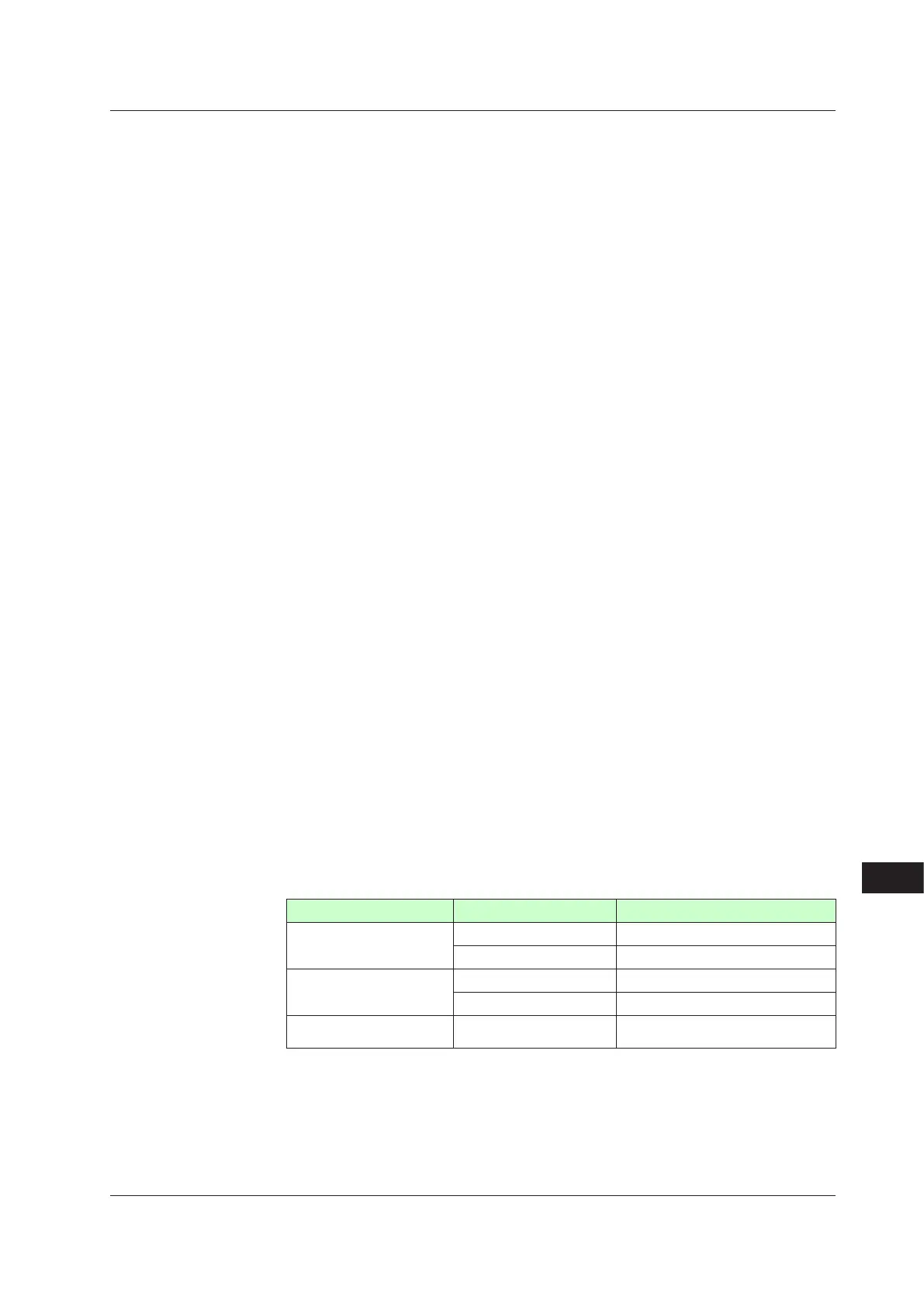
Input Type InstrumentRange Accuracy
Standard Signal
0.400 to 2.000
V ±0.2%ofinstrumentrange±1digit
1.000 to 5.000V ±0.1%ofinstrumentrange±1digit
DCVoltage
0.000 to 2.000V ±0.2%ofinstrumentrange±1digit
0.00 to 10.00V ±0.1%ofinstrumentrange±1digit
DC voltage for high-input
impedance
0.000 to 1.250V ±0.1%
ofinstrumentrange±1digit
• Input sampling (control) period: Same as universal input
• Inputresistance:About1MΩ
However,10MΩormoreforDCvoltageforhigh-inputimpedancerange
• Burnout detection: Functions at standard signal
Burnoutisdeterminedtohaveoccurredifitis0.1Vorless.
19.1HardwareSpecifications

 Loading...
