4-2
IM 05P01C31-01EN
The display pattern of the UT55A/UT52A is as follows; the Menu Display and Parameter
Setting Display.
For the Operation Display, see Chapter 6, “Monitoring and Control of Regular
Operations.”
Display Description
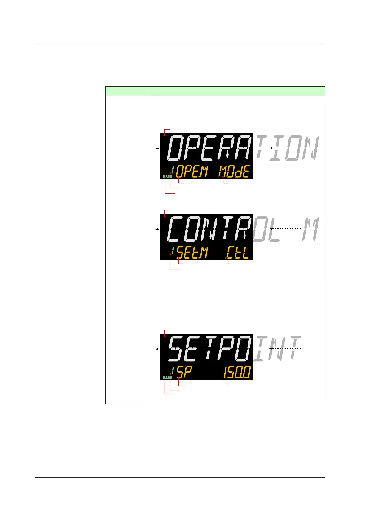
Menu Display
The Menu Display is segmented by the function and optional terminal position.
Thescrollingguide
forthemenuisdisplayedonPVdisplay.Theguidedisplay
can be turned on/off with the Fn key.
Menu Display of Operation Parameter
Group number or Terminal area is displayed.
Lit while Loop-2 parameter is displayed.
OPE.M is displayed.
Menu symbol is displayed.
The scrolling guide for the menu is displayed.
Menu Display of Setup Parameter
Group number or Terminal area is displayed.
SET.M is displayed.
Menu symbol is displayed.
The scrolling guide for the menu is displayed.
Parameter
Setting Display
The following is the Display for displaying and setting a parameter.
The parameters have three types of display levels; Easy setting mode,
Standard setting mode, and Professional setting mode. The parameters to be
displayed can be limited according to the setting of the parameter display level.
Thescrollingguide
fortheparameterisdisplayedonPVdisplay.Theguide
display can be turned on/off with the Fn key.
Parameter Setting Display (Example of Operation Parameter Setting Display)
Group number or Terminal area is displayed.
Lit while Loop-2 parameter is displayed.
Setpoint is displayed.
Parameter symbol is displayed.
The scrolling guide for the parameter is displayed.
4.1OverviewofDisplaySwitchandOperationKeys

 Loading...
