Program Pattern Number Display (Display only)
Parameter RMS = PROG
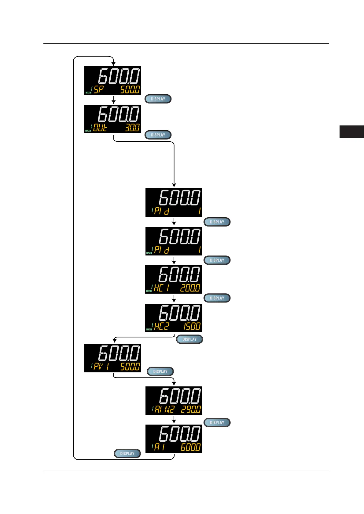
PV display: Loop-1 PV
Loop-2 SP Display (SP can be changed.)
PV display: Loop-2 PV
LP2 lamp is lit.
Loop-2 OUT Display (OUT can be changed.)
PV display: Loop-2 PV
LP2 lamp is lit.
Loop-1 PID Number Display (display only)
(Factory default: non-display)
PV display: Loop-2 PV
Heater Break Alarm-1 Current Display (display only)
(Only for Heater break alarm option)
PV display: Loop-2 PV
LP2 lamp is lit.
Heater Break Alarm-2 Current Display (display only)
(Only for Heater break alarm option)
PV display: Loop-2 PV
LP2 lamp is lit.
SELECT Displays 1 to 5
(Displayed only when SELECT Display is registered.)
(The figure on the left is the example of
the parameter A1 (alarm-1 setpoint).)
PV display: Loop-2 PV
Loop-2 PID Number Display (display only)
(Factory default: non-display)
PV display: Loop-2 PV
LP2 lamp is lit.
Loop-2/Loop-1 PV Display (display only)
PV display: Loop-2 PV
Setpoint display: Loop-1 PV
Analog Input Displays (display only)
(Factory default: non-display)
PV: PV analog input,
RSP: RSP analog input (E1-terminal area),
AIN2: AIN2 analog input (E2-terminal area),
AIN4: AIN4 analog input (E4-terminal area)
(Only for each aux. analog input)

 Loading...
