6-14
IM 05P01C31-01EN
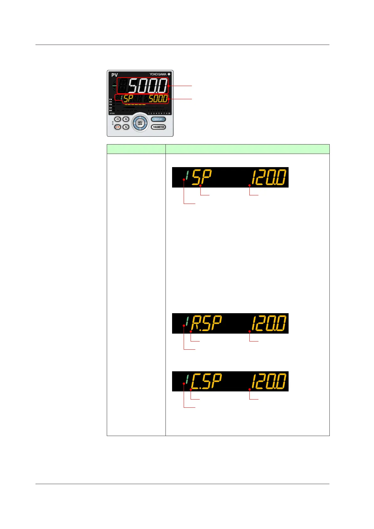
DetailsoftheOperationDisplay
The following is the Operation Display types and each display and operation description.
PV display
Setpoint display
OperationDisplay Display and operation description
SP Display
PVdisplay:Displaysmeasuredinputvalue(PV).
Setpoint display: Displays and changes target setpoint (SP).
Symbol
Target setpoint (SP) number
Target setpoint
The Display is switched to the SP Display if the operation mode is
switched to AUTO, CAS, LCL, or REM when other Operation Display is
shown.
[SPChangeOperation]
(1) Press the SET/ENTER key to move to the setting mode (the setpoint
blinks).
(2) Use the Left or Right arrow key to move between digits (the setpoint
blinks).
(3) Use the UP or Down arrow key to change the value (the setpoint
blinks).
(4)
Press the SET/ENTER key to register the setpoint. (the setpoint stops
blinking).
* Only Up or Down arrow key operation is also possible.
When the operation mode is remote (REM lamp is lit):
Target setpoint (SP) number in LOCAL mode
Remote setpoint
Symbol
When the control mode is Cascade secondary-loop control and the
operation mode is cascade (CAS lamp is lit):
Cascade setpoint
Target setpoint (SP) number in LOCAL mode
Symbol
When the control mode is Cascade secondary-loop control and the
operation mode is AUTO or MAN, the Loop-2 SP is displayed.
6.1MonitoringandControlofOperationDisplays

 Loading...
