Site Preparation and Installation 3 - 17
Cutout/Dimensions - MP70XX Long (continued)
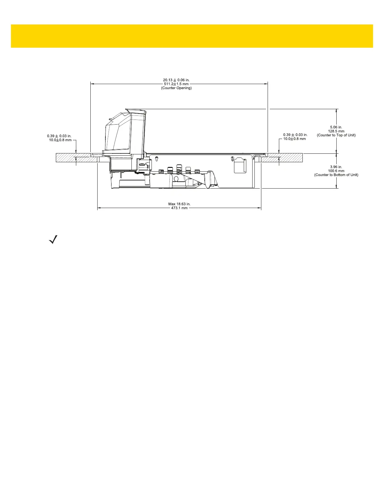
Figure 3-18 Long Unit Side View Dimensions
To install the MP70XX:
1. Ensure the following items were completed:
a. Existing scanner and accessories were removed, if applicable. See
Remove Existing Scanner Scale and
Accessories on page 3-6.
b. Cables were connected and routed. See Cables and Connections on page 3-10.
c. The Scale Display was installed, if applicable. See Install the Scale Display on page 3-8.
d. CSS was installed, if applicable. See Install the MX101 on page 3-11.
e. Sensormatic coil, or Checkpoint EAS antenna was installed, if applicable. See Install the Sensormatic Coil
Antenna on page 3-20, or Install the Checkpoint Antennas on page 3-22.
2. Verify checkstand dimensions shown in
Figure 3-8, Figure 3-12, and Figure 3-16, respectively.
NOTE The countertop, after routing, must have sufficient strength to support the scanner and the loads placed on top
of it. If the countertop is not strong enough, add strengthening supports underneath the countertop as
required.